


Maintenance
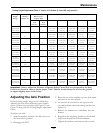
Cutting Height Adjustment Table (1 inch to 4 1/4 inches (2.5 cm-10.8 cm)) (cont'd.)
Number Of Spacers
Below Caster
Support Hub
Number of 1/4 inch (.64 cm) Blade Spacers Below Spindle
Cutting
Height
Range
Axle
Position
(Figure 11)
1/2
inch
(1.2 cm)
3/16
inch
(.48 cm)
4
3 2
1 0
2 1/8–
3 1/8 inches
(5.4–7.9 cm) C 2 0
2 1/8 inch
(5.4 cm)
2 3/8 inch
(6.0 cm)
2 5/8 inch
(6.7 cm)
2 7/8 inch
(7.3 cm)
3 1/8 inch
(7.9 cm)
2 1/4–
3 1/4 inches
(5.7–8.3 cm) C 2 1
2 1/4 inch
(5.7 cm)
2 1/2 inch
(6.4 cm)
2 3/4 inch
(7.0 cm)
3 inch
(7.6 cm)
3 1/4 inch
(8.3 cm)
2 1/2–
3 1/2 inches
(6.4–8.9 cm) C 3 0
2 1/2 inch
(6.4 cm)
2 3/4 inch
(7.0 cm)
3 inch
(7.6 cm)
3 1/4 inch
(8.3 cm)
3 1/2 inch
(8.9 cm)
2 3/8–
3 3/8 inches
(6.0–8.6 cm) D 2 1
2 3/8 inch
(6.0 cm)
2 5/8 inch
(6.7 cm)
2 7/8 inch
(7.3 cm)
3 1/8 inch
(7.9 cm)
3 3/8 inch
(8.6 cm)
2 1/2–
3 1/2 inches
(6.4–8.9 cm) D 3 0
2 1/2 inch
(6.4 cm)
2 3/4 inch
(7.0 cm)
3 inch
(7.6 cm)
3 1/4 inch
(8.3 cm)
3 1/2 inch
(8.9 cm)
2 3/4–
3 3/4 inches
(7.0–9.5 cm) D 3 1
2 3/4 inch
(7.0 cm)
3 inch
(7.6 cm)
3 1/4 inch
(8.3 cm)
3 1/2 inch
(8.9 cm)
3 3/4 inch
(9.5 cm)
3–4 inches
(7.6–10.1 cm) D 4 0
3 inch
(7.6 cm)
3 1/4 inch
(8.3 cm)
3 1/2 inch
(8.9 cm)
3 3/4 inch
(9.5 cm)
4 inch
(10.1 cm)
2 7/8–
3 7/8 inches
(7.3–9.8 cm) E 3 1
2 7/8 inch
(7.3 cm)
3 1/8 inch
(7.9 cm)
3 3/8 inch
(8.6 cm)
3 5/8 inch
(9.2 cm)
3 7/8 inch
(9.8 cm)
3 1/8–
4 1/8 inches
(7.9–10.5 cm) E 4 0
3 1/8 inch
(7.9 cm)
3 3/8 inch
(8.6 cm)
3 5/8 inch
(9.2 cm)
3 7/8 inch
(9.8 cm)
4 1/8 inch
(10.5 cm)
3 1/4–
4 1/4 inches
(8.3–10.8 cm) E 4 1
3 1/4 inch
(8.3 cm)
3 1/2 inch
(8.9 cm)
3 3/4 inch
(9.5 cm)
4 inch
(10.1 cm)
4 1/4 inch
(10.8 cm)
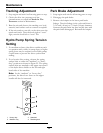
Important: Always adjust the Number of Spacers below Caster Hub to correspond to the Axle
Position as shown in table to obtain proper “rake” (blades should always be level to the ground
or tipped slightly down at the front).
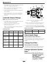
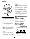
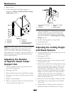
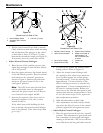
Adjusting the Axle Position
Desired cutting height range can be obtained by
adjusting the rear axle and placing caster spacers
above or below the caster arm (see Figure 11 and
Figure 12 along with the Cutting Height Adjustment
Chart).
To adjust rear axle:
1. Stop the machine and move the drive levers to
the neutral lock position.
2. Disengage the PTO.
3. Raise the rear of the machine up onto jack stands
and remove the drive wheels.
4. Loosen but do not remove the top two bolts
on each hydraulic motor mounting bracket (see
Figure 11).
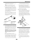
5. Remove the bottom sets of hardware for each
bracket.
6. Reposition the mounting bracket to the desired
height and reinstall the bottom hardware.
7. Tighten all hardware and remount drive wheels.
29