


Reference Manual
MAN-0081, Revision 4 July 2014
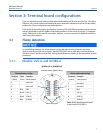
11
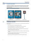
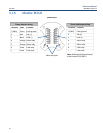
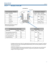
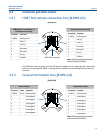
3.1.7 Models: IR3S-AR
By default the Fault relay is fixed as Energized and Non-latching and cannot be changed. The default
setting for the Alarm relay is De-energized and Non-latching. The current loop jumper pins at J6 are
not jumpered by default.
If 4-20 mA is not being used close the loop by placing the current loop jumper over pins (short J6).
To reset latched alarm, connect Reset (Terminal 1) to ground, recycle power or activate Reset
magnetic switch using the magnet.
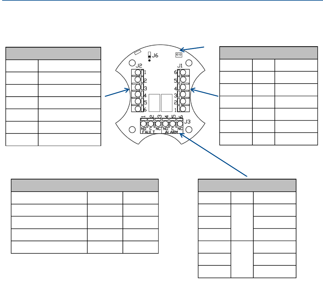
DIP Switch
Flame detector wiring (J1)
Terminal
Color
Function
1 (GND)
Green
Earth ground
2
Red
Vdc (+)
3
Not used
4
Black
COM (-)
5
Purple
ISO (+)
6
Yellow
4-20mA
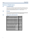
Power and output wiring (J2)
Terminal
Function
1
Reset
2
4-20mA
3
ISO (+)
4
COM (-)
5
Not used
6
Vdc (+)
JB-IR3SAR-A/S
Note: Shield should be terminated
at the Panel/PLC/DCS/RTU
Relay wiring
Terminal
Relay
Contact state
1
Fault
NO
2
Common
3
NC
4
Alarm
NO
5
Common
6
NC
Coil and latch status (DIP switch)
Alarm relay
Position 1
Position 2
De-energized/non-latching
On
On
Energized/non-latching
On
Off
De-energized/latching
Off
On
Energized/latching
Off
Off