


©2005 Edelbrock Corporation
Brochure #63-0434
Catalog #71884
Rev. 12/05 - DC/mcPage 3 of 4
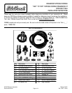
9. Find a secure location to mount the Performer
Nitrous Solenoid assembly within reach of the
nitrous feed line and the dry nitrous nozzle. Make
sure that this location is away from moving objects
and will not interfere with closure of the hood.
10. Connect the nitrous feed line to the INLET fitting of
the Performer Nitrous Solenoid. DO NOT use any
thread sealant, since AN fittings are designed as
dry seal fittings.
11. Using your existing blue 3AN line, connect one end
of the line to the OUTLET fitting on the Performer
Nitrous Solenoid.
12. Place the .032” nitrous jet in the EFI nitrous nozzle.
Attached the free end of the blue 3AN line to this
fitting with the jet in place. DO NOT use any type
of thread sealant for this connection.
13. Take the new EFI Vacuum Tee that is supplied with
this kit, and make sure that the .042” jet is installed.
14. Remove the vacuum line from the vehicles fuel
pressure regulator. Install this line on the center
barb of the EFI Vacuum Tee. (NOTE: The center barb
can easily be identified by the anodized nut used to
hold the Fuel Jet.)
15. Measure the correct length of vacuum line from the
barb on the Fuel Pressure Regulator to one port of
the EFI Vacuum Tee. Cut the vacuum line and
install.
16. Measure the correct length of vacuum line from the
barb fitting to the nitrous pressure regulator to the
remaining open port of the EFI vacuum tee. Cut
vacuum line and install.
This concludes the installation of the hardware for your
Dry Nitrous System. After performing these steps, it is
time to do a pressure check on all of the components
that you just installed before completing the system
wiring.
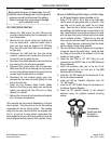
You should check the nitrous system. This should be
checked with the engine OFF. Make sure that all fittings
are tight. Slowly open the bottle valve and walk back
around to the engine compartment. Listen carefully for
leaks. Leaks can be noticed by a slight hissing sound or
by ice forming around fittings. You should hear no
sounds coming from fittings or lines if everything is
connected properly. If leaks are noticed, tighten the
fittings until the leaks seal.
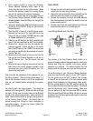
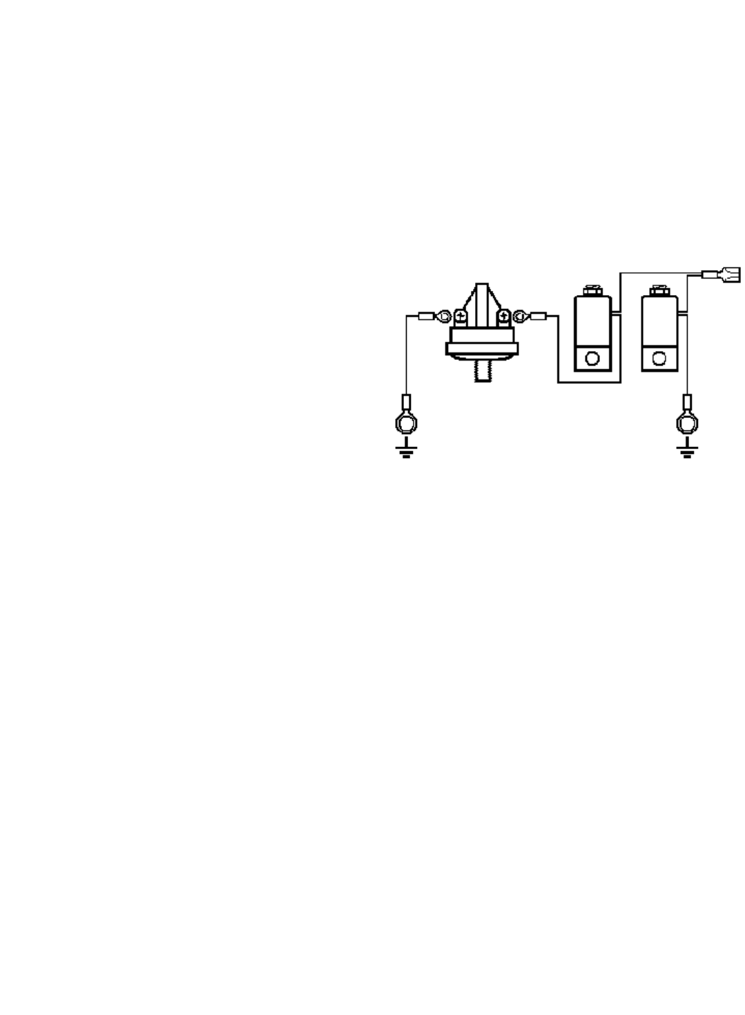
FINAL WIRING
1. Connect one wire from each solenoid to the BLUE wire
routed from the relay wiring harness.
2. Ground the inlet solenoid (the nitrous solenoid that the
feed line leads into) directly to a chassis ground.
3. Connect the remaining wire from the outlet solenoid
(the nitrous solenoid that feeds the nozzle) to the fuel
pressure safety switch.
4. Connect a wire from the remaining terminal of the fuel
pressure safety switch to a chassis ground.
Your Wiring Should Look Like This..
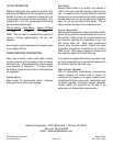
The purpose of the Fuel Pressure Safety Switch is to
prevent the safety solenoid (second solenoid in line) from
opening and filling the manifold with nitrous without
adequate fuel pressure. This switch monitors the fuel
pressure and only actuates over a pre-set fuel pressure.
To test the wiring of your Performer Nitrous Solenoids,
make sure that the bottle valve is in the “OFF” position.
Turn the ignition key to the “ACC.” position. Use a jumper
to connect the two terminals of the fuel pressure safety
switch, therby bypassing the fuel pressure safety switch.
With the arming switch in the “ON” position, quickly tap
the microswitch button to activate the system. You should
hear the first solenoid “click” if wired correctly. Make sure
that you perform this test with the valve OFF to prevent
filling the manifold with Nitrous Oxide. Be sure to remove
the jumper from the fuel pressure safety switch once done
testing the wiring.
To BLUE
wire from
harness
Ground
Ground
First
Nitrous
Solenoid
Second
Nitrous
Solenoid
Fuel Pressure
Safety Switch