


INSTRUCTIONS FOR ENGINE PARTS REMOVAL
• BEFORE CAMSHAFT INSTALLATION
1. Disconnect battery.
2. For ease of installation, keep all parts in some sort of order.
WARNING: Do not remove radiator cap or radiator hose if
engine is hot.
3. Drain radiator coolant, move fan shroud back and remove fan
and spacer from water pump. On air conditioned vehicles,
remove bolt, lower idler pulley and compressor-to-water pump
mount. Disconnect hoses and brackets. Most vehicles will
require radiator removal prior to cam removal. Remove water
pump.
4. Disconnect all linkage from carburetor such as throttle, throttle
springs, transmission, cruise control and automatic choke
5. Tag and remove vacuum lines.
6. Remove valve covers.
7. Remove distributor cap and wires, rotate engine until rotor
points towards number 1 terminal in cap and pointer on front
cover is on Top Dead Center (TDC) and remove distributor.
Note the approximate position of the vacuum advance canister
in relation to the manifold to assist in getting the distributor
properly located during re-installation.
8. Remove carburetor and intake manifold. Remove fuel pump.
9. Remove rocker arms and pushrods.
10.Remove hydraulic valve lifters.
11.Remove crankshaft pulley and, using a suitable puller, crank-
shaft dampener.
12.Loosen oil pan and remove front cover.
NOTE: The front cover oil seal should be replaced before the
front cover is re-installed.
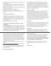
13.Rotate engine until timing marks are aligned as shown in Figure
2.
14.Remove cam sprocket bolt, washer, and fuel pump eccentric.
Slide sprocket and timing chain forward to remove.
15.Remove camshaft thrust plate noting location of oil tab. Install
a long bolt in front of camshaft to facilitate removal and care-
fully remove camshaft. Using appropriate gear puller, remove
crank sprocket.
• VALVE SPRINGS
CAUTION: WARNINGS ABOUT YOUR WARRANTY
In order for this Performer RPM cam and lifter kit to be cov-
ered under ANY WARRANTY you MUST use the correct
Edelbrock Sure Seat Valve Springs. Failure to install new
Edelbrock valve springs with your new Performer RPM cam
could cause the cam lobes to wear excessively and could cause
additional engine damage.
1. This camshaft is designed to function with Edelbrock Sure Seat
valve springs #5777. Do not use dual valve springs with this
camshaft. Special H.P. retainers may be necessary with your
installation for proper spring height. Do not use rotator type
valve springs or retainers for this application.
• LIFTERS
1. New lifters must be used with new camshaft. Use only the high
rev lifters supplied with this kit.
2. Check to be sure that all lifters fit freely in the lifter bores and
that the factory did not install oversized lifters in your block to
compensate for machining errors.
• INSTALLATION INSTRUCTIONS
1. Coat cam lobes and bottoms of each lifter with MoS2 lube
(supplied) to prevent cam lobe and lifter wear from occurring
during initial start-up.
2. Install new camshaft with new sprockets, timing chain and
lifters.
CAUTION: Use Edelbrock Performer-Plus True Rolling
Timing Chain and Steel Gear Set #7803. Do not use late model
timing chain & gear sets that are designed in a retarded position
and are not recommended for this camshaft installation.
Edelbrock Timing Sets feature three keyways for specific tim-
ing selection. Use locking compound material on the bolt
threads holding timing gear to cam. Torque to factory recom-
mendations specified in motor repair manual.
Install camshaft with timing marks lined up as recommended by
factory specifications. See Figure 2.
When using Performer-Plus Timing Chain and Gear Sets (7800
series) with Edelbrock cam and lifter kits, straight up timing
alignment is achieved. If any other timing gear set is used, it is
necessary to check cam position for correct timing alignment.
This requires indexing the camshaft with a degree wheel to ver-
ify timing alignment. O.E.M. or non-Edelbrock timing gear sets
are not recommended for use with Edelbrock camshafts.
• INSTALLING PUSHRODS AND ROCKER ARMS
High performance pushrods and rocker arms are recommended
for this installation.
After the cam is installed and timed correctly (see Figure 2), it
will be necessary to check each pushrod for correct lifter pre-
load.
• VALVE ADJUSTMENT
1. Turn the engine over until the No. 1 cylinder exhaust lifter
starts to move up. Adjust intake rocker arm to zero clearance
between rocker arm and valve tip. From this point turn adjust-
ing nut down (clockwise) 1/4 turn more for final adjustment.
2. Turn the engine over again until the intake lifter just stops com-
ing down. Adjust exhaust rocker arm to zero clearance between
rocker arm and valve tip. From this point turn adjusting nut
down (clockwise) 1/4 turn more for final adjustment.
3. The above procedure assures correct hydraulic lifter preload.
Repeat this procedure for each of the other seven cylinders.
4. Re-install front cover, fuel pump, water pump, and oil pan
using new gaskets.
5. Install intake manifold using new intake gasket set and torque
manifold bolts to 25 ft./lbs. CAUTION: Remove front and rear
seal dowel pins in block if so equipped.
6. Install crankshaft dampener and torque to factory specifications.
• INSTALLING DISTRIBUTOR AND TIMING ENGINE
NOTE: Before installing your distributor, check the gear drive
on the distributor and oil pump for any signs of wear. If worn,
be sure to replace with new or you may wear out your camshaft
prematurely. This is especially true when rebuilding your
engine and a high performance oil system is used, which gener-
ates a heavier load on the camshaft gear system. Edelbrock
camshafts are designed to use OEM-type gears only.
1. Turn the engine over in the direction of rotation until the No. 1
intake valve closes and continue until the pointer on the front
cover is approximately 5 degrees BTDC.
2. Re-install the distributor with the rotor pointing towards No. 1