


©2002 Edelbrock Corporation
Rev. 10/02
Brochure No. 63-0126
Catalog #70206
Page 3 of 4
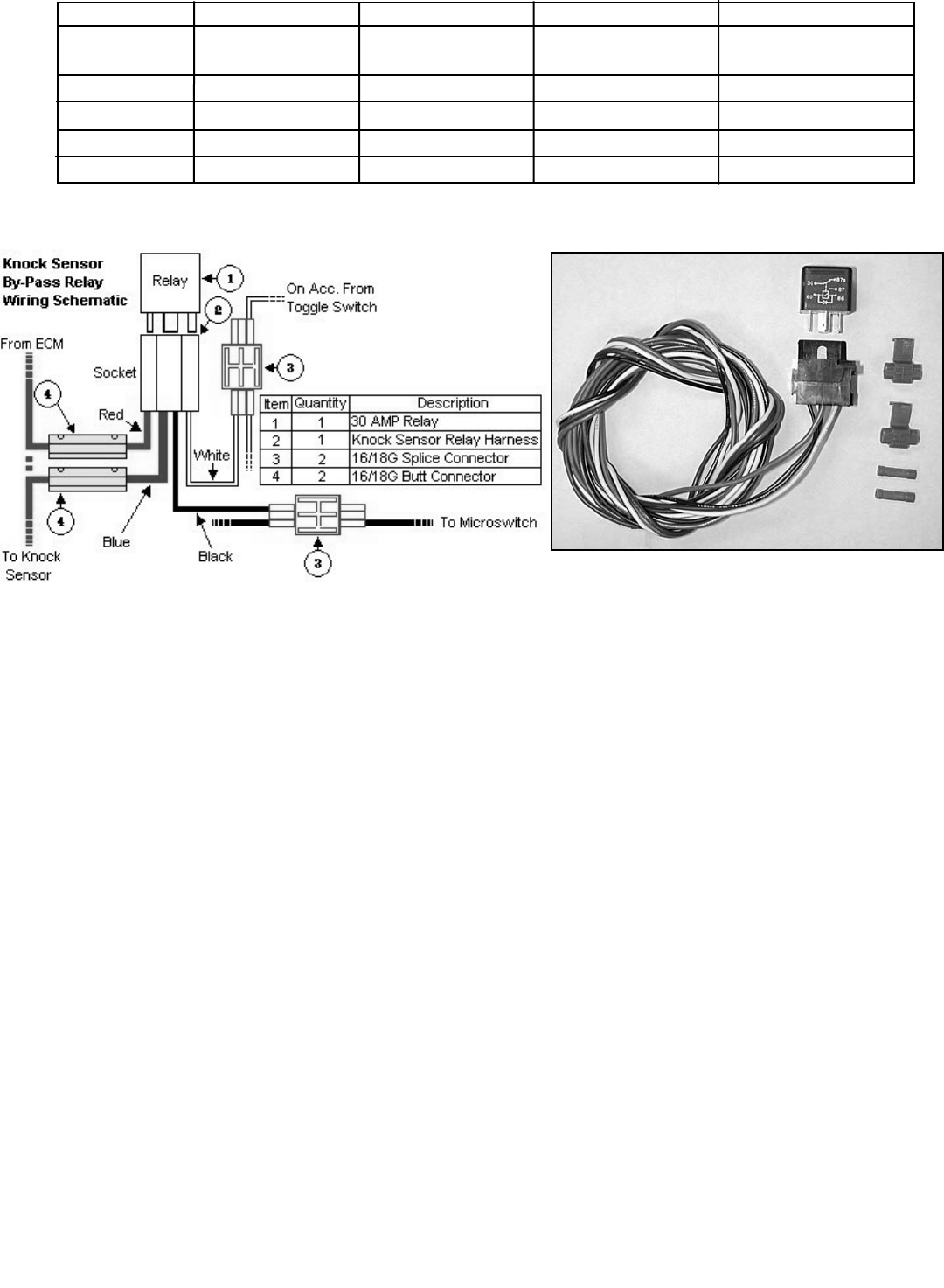
Knock Sensor By-Pass Relay Installation
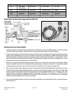
1. Determine the location of the Knock Sensor By-Pass Relay. This should be as close to the ECM as possible. Since the connectors
are water-resistant, not waterproof, mount the relay in a location with minimal chance of exposure to water.
2. The wire harness attached to the relay includes 4 feet of color-coded wires to make the electrical system installation as easy as
possible. We recommend that you do not cut any lengths of wires from the wire harness or complete the wiring of the nitrous
system until all of the mechanical components are securely mounted in their permanent locations. Do not exceed the 4 feet of
wire to the ECM and the knock sensor, this could send a faulty signal and the system would not work at optimal power. You can
extend the white and black wires beyond the 4 feet if necessary.
3. Once all of the system components have been mounted, route the un-cut wires from the harness to each location allowing
enough wire length on each circuit to not interfere with operating linkages, heat sources, brackets, etc. Pay particular attention
to sharp edges along the route of your wire harness as they can chafe the wires and cause your system to fail.
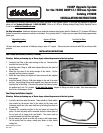
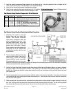
4. After you have accounted for the routing of your wires, follow the Knock Sensor By-Pass Relay Wiring Schematic above and use
the Wire Schematic Origin and Destination Map below as a guide for which electrical connectors are used in each circuit. Note
that the one wire from the ECM to the Knock Sensor needs to be cut and intercepted with the relay. This wire on 1994-1997
Camaros, Firebirds, and Impalas is located on the BLUE terminal in pin location #22. It is a blue wire. On 1993 Camaros and
Firebirds, this wire in located on the GREEN ECM connector C terminal in pin location C8. It is a dark blue wire. Try to keep the
Knock Sensor By-Pass Relay as close to this wire as possible.
5. Once you have decided the location of the relay, secure them with fasteners (not included with kit) such as sheet metal screws,
nuts and bolts, etc.
Wire Color System Origin Destination Terminal Used
Red Main Booster Relay Harness Bat. Volt. Signal 3/8” Ring
Pump Bat. Volt.
Blue Fuel Pump Power Relay Harness Fuel Booster Pump #8 Ring
Black Fuel Pump Ground Fuel Booster Pump Chassis Ground #8 Ring / 3/8” Ring
White Relay Power Relay Harness Arming Switch Splice Conn.
Black Relay Ground Relay Narness Chassis Ground 3/8” Ring
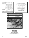
Knock Sensor By-Pass Relay Components Bill of Material