


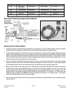
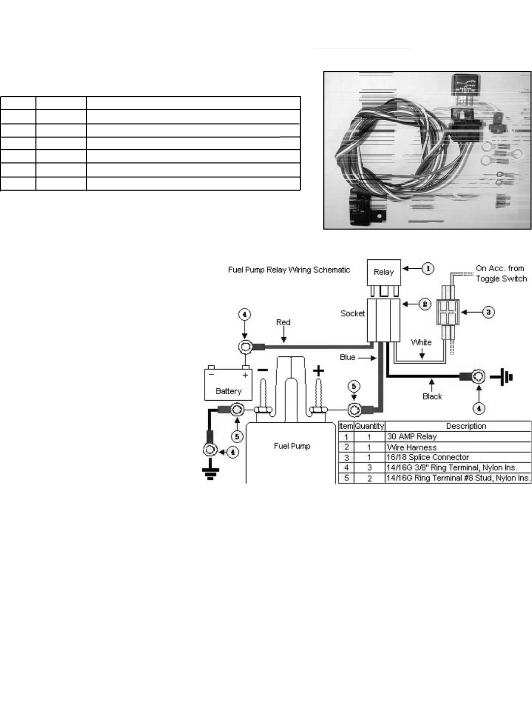
Fuel Booster Pump Electrical Components Bill of Materials
Item # Quantity Description
1 1 ea. 30 amp relay
2 1 ea. Wire harness with integral relay/fuse holder
3 1 ea. 16/18g splice connector
4 1 ea. 14/16g 3/8” ring terminal, Nylon insulated
5 1 ea. 14/16g ring terminal #8 stud, Nylon insulated
6 1 ea. 15 amp ATO blade fuse
©2002 Edelbrock Corporation
Rev. 10/02
Brochure No. 63-0126
Catalog #70206
Page 2 of 4
Fuel Booster Pump Electrical System Installation Procedures
1. Determine the location of the Fuel
Booster Relay and Fuse Holder Wire
Harness. Most common installations
locate these components inside the
driver’s compartment and close to the
fuse panel under the dash. You can also
mount the relay and fuse holder and
harness close to the battery. However,
these connectors are water-resistant, not
water-proof, so care is required when
mounting this assembly under the hood
of your vehicle.
2. The wire harness attached to the relay
and fuse holder includes 8 feet of color-
coded wires to make the electrical
system installation as easy as possible.
We recommend that you do not cut any
lengths of wires from the wire harness or complete the wiring of the fuel booster pump until all of the mechanical components
are securely mounted in their permanent locations.
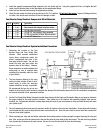
3. Use the Fuel Pump Relay Wiring Schematic located above along with the Origin and Destination Map on next page to determine
the proper routing for the wires and their locations. Take caution as to not interfere with operating linkages, heat sources,
brackets, etc. Pay particular attention to sharp edges along the route of your wire harness as they can chafe the wire and cause
your system to fail.
4. Once all components have been securely mounted, decide the location of the relay and fuse holder. Secure them with fasteners
(not included with kit) such as sheet metal screws, nuts and bolts, etc. Allow for some slack in the red wire that connects the
relay and fuse holder together.
5. When mounting your relay and fuse holder, make sure the mounting surface is strong enough to support servicing the relay and
fuse. Also, ensure you allow for some slack in the wire that joins the fuse holder to the relay mount. This will avoid any potential
loss of power due to stress on the wire harness. Be sure to cover the fuse with the fuse mount housing.
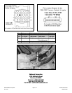
4. Install the supplied compression fitting adapters to the cut plastic fuel line. Using the supplied fuel line, cut lengths that will
reach from the booster pump to the hose barbs on the compression fittings.
5. Install cut fuel lines and secure using the supplied hose clamps.
6. Check the fuel system for leaks by turning the key to the “On” position. Do not start the engine
. Inspect all fittings and lines
for leaks. Also check wires from time to time for damage or leaks.