


Catalog #70080, #70081, #70082, #70083
Brochure No. 63-0312
©2008 Edelbrock Corporation
Rev. 07/08
Page 17
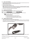
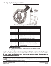
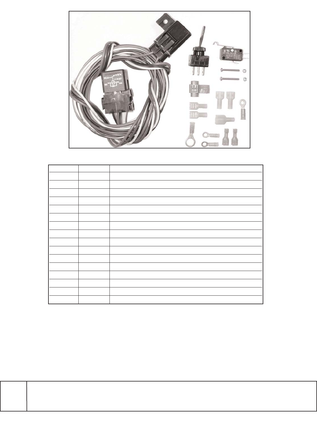
2.12 Single Stage Electrical System Installation
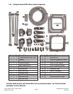
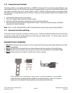
Nitrous Electrical Components Bill of Materials (BOM)
Item # Quantity Description
1 1 ea. Activation microswitch
2 1 ea. Activation microswitch bracket (not shown)
3 2 ea. Activation microswitch mounting nut
4 2 ea. Activation microswitch mounting screw
5 1 ea. 30 amp relay
6 1 ea. Wire harness with integral relay/fuse holder
7 1 ea. Red lighted toggle switch
8 2 ea. 18/22g female spade connector, Nylon insulated
9 2 ea. 14/16g female spade connector, Nylon insulated
10 1 ea. 14-16g male spade connector, Nylon insulated
11 1 ea. 16/18, splice connector
12 1 ea. 14/16g 3/8” ring terminal, Nylon insulated
13 3 ea. 18/22g ring terminal #10 Stud, Nylon insulated
14 2 ea. 18/22g ring terminal #8 Stud, Nylon insulated (.187)
15 2 ea. 18/22g female spade connector, Nylon insulated (.187)
16 1 ea. 15 amp ATO blade fuse
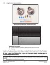
Nomenclature Descriptions:
ATO… the fuse configuration is ATO. When replacing this fuse, ask for an ATO fuse.
“a”… Amperage.
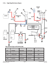
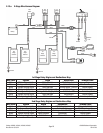
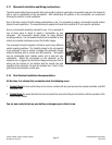
Important: The wiring hardware and instructions included with this kit are intended for 12-volt electrical
systems only. Before attempting to wire your Edelbrock Performer nitrous oxide system, examine and follow
the wiring diagram on the following page. Please call the Edelbrock Technical department with any
questions concerning electrical wiring.
When working with electrical systems in your vehicle, it is a good idea to have a service manual that features
your vehicle. It is also good practice to have a book that specializes on the specialized techniques required
when working with vehicular electrical systems.