


Catalog #70005
Rev. 07/08 - AJ/mc
©2008 Edelbrock Corporation
Brochure No. 63-70005
Page 9 of 20
2.0 Nitrous System Installation
2.1 Installation Instructions
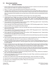
1. Disconnect both the nitrous and fuel lines leading from the solenoids to the plate. Be careful not to lose the nitrous and fuel jet
that you currently have installed in the system when removing these lines.
2. Using a 7/16” wrench or socket remove both the nitrous inlet fitting and the fuel inlet fitting.
3. Thoroughly clean the threaded holes of the plate that are exposed after removal of the inlet fittings. Make sure that there is no
metal debris in these holes and that they are free of thread sealant or locking compound. Make sure that no debris falls into the
nitrous or fuel spray bars. After cleaning the area, use a shop vacuum or other vacuum to suction any remaining debris from the
inlet areas.
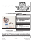
4. Place a small bead of Teflon Paste, NOT TEFLON TAPE, around the thread of each of the supplied Y-Fittings.
5. Carefully thread the new Y-Fittings into the inlet ports of the plate. Make sure that the blue Y-Fitting gets installed in the port
labeled ‘Nitrous’ and the red Y-Fitting gets installed in the port labeled ‘Fuel’. Using a 7/16” wrench, tighten these fitting into the
plate while being careful not to over-tighten and strip the threads out of the plate. The Teflon Paste should form a nice bead
completely around the port to help ensure a good seal.
6. Place a small bead of Teflon Paste around the threads on the blue 4AN to 1/8”NPT fitting supplied in the kit. Thread this fitting
into the OUTLET port of the supplied Performer Nitrous Solenoid.
7. Place a small bead of Teflon Paste around the threads on the blue 4AN to 1/8”NPT filter fitting supplied in this kit. Thread this
fitting into the INLET port of the supplied Performer Nitrous Solenoid.
8. Secure the Performer Nitrous Solenoid in a bench vise and tighten both the inlet and outlet fittings being careful not to over-
tighten and strip the threads.
9. Place a small bead of Teflon Paste around the threads on the red 4AN to 1/8”NPT fitting supplied in this kit. Thread this fitting
into the OUTLET port of the supplied Performer Fuel Solenoid.
10. Place a small bead of Teflon Paste around the threads on the red 4AN to 1/8”NPT fitting supplied in this kit. Thread this fitting
into the INLET port of the supplied Performer Fuel Solenoid.
11. Secure the Performer Fuel Solenoid in a bench vise and tighten both the inlet and outlet fittings being careful not to over tighten
and strip the threads.
12. Using the supplied solenoid brackets and solenoid mounting screws, mount the solenoids within reach of the jet fittings on the
plate using the supplied blue 4AN to 3AN 12” hose for nitrous and red 4AN to 3AN 8” hose for fuel.
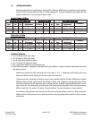
13. Choose your intended horsepower settings from the jetting chart on page 6. Find the first stage jetting that you intend to run in
the supplied jet bag that comes with this kit. Use the jets supplied in the jet pack for your Performer RPM Nitrous System for
the second stage jets.
14. Place the first stage nitrous jet in one of the inlet ports of the blue nitrous Y-Fitting of the plate closest to the Performer Nitrous
Solenoid. Install one of the 12” Blue 3AN to 4AN lines from the outlet fitting of the Performer Nitrous Solenoid to the fitting
containing the first stage nitrous jet. Snug down both ends of this line but do not over tighten to prevent stripping.
15. Place the first stage fuel jet in one of the inlet ports of the red fuel Y-Fitting of the plate closest to the Performer Fuel Solenoid.
Install one of the 8” Red 3AN to 4AN lines from the outlet fitting of the Performer Fuel Solenoid to the fitting containing the first
stage fuel jet. Snug down both ends of this line but do not over tighten to prevent stripping.
16. Place the second stage nitrous jet in the remaining open inlet fitting of the blue nitrous Y-Fitting. Install the line as described in
step 14 but to the Performer RPM Nitrous Solenoid.
17. Place the second stage fuel jet in the remaining open inlet fitting of the red fuel Y-Fitting. Install the line as described in step 15
but to the Performer RPM Fuel Solenoid.
18. Using the two red 4AN fuel lines and red 4AN Y-Fitting supplied with this kit, connect each solenoid to the Y-Fitting.
19. Connect the fuel line that was originally connected to your Performer RPM Solenoid to the inlet of the red 4AN Y-Fitting.
20. Repeat steps 18 and 19 using the blue lines and Blue Y Fitting for the nitrous solenoids.
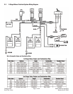
21. Wire per the diagram on page 11.