


Catalog #68752, 68753
©2006 Edelbrock Corporation
Page 3 of 3
Brochure #63-68752
Rev. 6/06 - DA/mc
Edelbrock Corporation, 2700 California St., Torrance, CA 90503
Tech Line: 1-800-416-8628
E-Mail: Edelbrock@Edelbrock.com
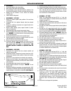
Small Umpco Clamp
10-32 Capscrew, Nut, and Washer
Large Umpco Clamp
.720” Spacer
Fig. 3
Right Side
Fig. 2
Left Side
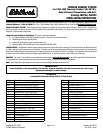
1.125” Spacer
1.530” Spacers
• CROSSOVER PIPE ASSEMBLY
1. Install crossover pipe assembly on vehicle using adapter and
gasket provided between right manifold and extension pipe.
NOTE: The gasket goes between the adapter and the manifold;
there is no gasket between the adapter and the extension pipe.
Use two 3/8" x 2" bolts with lock washers and donut gasket
supplied for the left side, and use two 3/8" x 3" bolts and lock
washers on the right side. Do not tighten at this time.
2. Form A.I.R. injection tube to catalytic converter. Align and
tighten all bolts and clamps.
• LOWER VEHICLE TO THE GROUND
1. Connect negative cable to battery. At this point, it would be a
good idea to look everything over and make sure nothing is
missed in assembly.
2. Start vehicle and bring up to normal operating temperature and
check for possible leaks.
3. Turn engine off and let cool. Tighten all bolts again.hose. Re-
connect all injection hoses at this time.