


Catalog #68752, 68753
©2006 Edelbrock Corporation
Page 2 of 3
Brochure #63-68752
Rev. 6/06 - DA/mc
• DISASSEMBLY
1. Disconnect negative cable from battery.
2. Raise vehicle and support with jackstands.
3. Use penetrating oil on all nuts and bolts to be removed. This
will prevent the possibility of broken or stripped nuts and bolts.
4. Making sure the converter is cool, remove the exhaust
crossover pipe.
5. Lower vehicle to the ground.
• DISASSEMBLY - LEFT SIDE
1. Remove air cleaner system (note position of line and hose
connections).
2. Disconnect A.I.R. (Air Injection Reactor) tube from exhaust
manifold.
3. Remove air conditioner compressor rear support bracket (if air
conditioning equipped).
4. Remove power steering pump support bracket (if power
steering is applicable).
5. Disconnect spark plug wires and remove spark plugs.
6. Remove O2 sensor, being careful not to rupture or destroy the
unit. WARNING: Do not clean this unit in any cleaning solvent
and do not rupture wire.
7. Disconnect temperature sensor wire at cylinder head.
8. Remove temperature sensor wire support bracket from valve
cover bolt and lay wire back over engine.
9. Remove bolts and exhaust manifold from top side.
10. Disconnect steering column connector and lower slip tube
down to steering box. CAUTION: Do not turn steering wheel or
front wheels while this system is disconnected. USE
EXTREME CAUTION IF VEHICLE IS EQUIPPED WITH AIR
BAG!
• DISASSEMBLY - RIGHT SIDE
1. Disconnect A.I.R. injection tube from exhaust manifold and
catalytic converter tube.
2. Disconnect electrical connector and vacuum hoses from A.I.R.
diverter valve assembly (note position of hose and electrical
connections).
3. Remove A.I.R. pump feed hose from diverter valve assembly.
4. Remove nut from diverter valve support bracket at exhaust
manifold and loosen alternator pivot bolt, then remove diverter
valve assembly.
5. Disconnect spark plug wires and remove spark plugs.
6. Remove dipstick and tube from engine. CAUTION: Do not
damage tube.
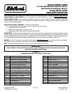
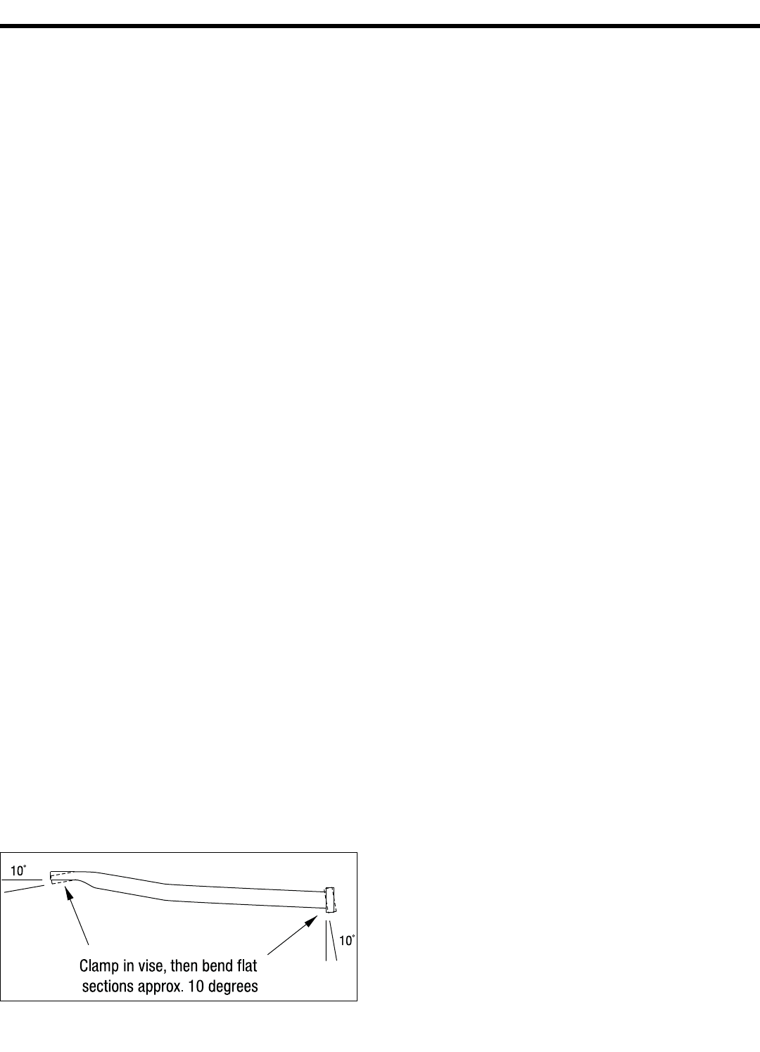
7. Remove air conditioner compressor rear support bracket. If A/C
compressor is mounted on right side of engine, this bracket will
require bending in a vise before re-installation
(See Figure 1).
INSTALLATION INSTRUCTIONS
8. Remove bolts and exhaust manifold from top side.
9. Clean exhaust flange surfaces on cylinder heads at this time.
10. Unbolt oil coolant tube from frame rail and bend brace around
tube. Bolt new flat brace (supplied) to frame rail. This will
move coolant tube above and on top of frame which will allow
more clearance for exhaust system.
• ASSEMBLY - LEFT SIDE
1. Install T.E.S. flange gasket and one 3/8"-16 x 1" bolt, lock
washer, and flat washer at rearmost bolt hole (leave bolt loose
enough to accept T.E.S.).
2. Install left side T.E.S. manifold from top side.
3. Install all but the front three bolts and washers on left side (do
not tighten at this time).
4. Re-install rear power steering support bracket (do not tighten at
this time).
5. Re-install rear A/C support bracket with bolts, lock washers,
and spacers supplied
(See Figure 2 for spacer locations).
6. Align all parts and tighten left side bolts and nuts at this time.
7. Re-connect steering column coupler. WARNING: Make sure
coupler bolt is tight and check to see that steering wheel is in
same orientation as prior to disassembly.
8. Form brake lines to clear TES pipes.
9. Re-install spark plugs and re-connect wires on left side.
10. Change spark plug wire ends and boots as needed.
11. Re-install temperature sensor wire support bracket and re-
connect wire to temperature sensor.
12. Re-install O2 sensor. Use anti-seize on threads of sensor and
torque to 30 ft./lbs. Re-route O2 sensor wire from wire loom to
O2 sensor making sure all wires are clear of exhaust system
(O2 sensor extension wire is included in kit).
• ASSEMBLY - RIGHT SIDE
1. Install T.E.S. flange gasket and one 3/8"-16 x 1" bolt, lock
washer and flat washer at rearmost bolt hole (leave bolt loose
enough to accept T.E.S.).
2. Install right side T.E.S. manifold and dipstick tube from top side.
3. Install remaining bolts, lock washers, and dipstick tube clamps
(See Figure 3).
Do not tighten bolts at this time.
4. Re-install O.E.M. front stud bolt with spacer (supplied). Align all
parts and tighten all right side bolts at this time.
5. Re-install spark plugs and re-connect wires.
6. Change spark plug wire ends and boots as needed.
7. Re-install diverter valve assembly in front O.E.M. stud bolt and
tighten.
8. Re-connect electrical connections and vacuum lines to diverter
valve assembly.
9. Remove A.I.R. check valves from original manifolds and re-
install them on T.E.S. For 1986 & 1987 models, use plastic
connector and 5" hose supplied. Re-connect air hoses. For
1988 models remove 1/2" from formed rubber O.E.M. elbow
and install plastic connector. Use 2" of hose supplied and re-
connect air hose. Re-connect all A.I.R. injection hoses at this
time.
10. Raise vehicle and support with jackstands.
Fig. 1