


©2007 Edelbrock Corporation
Brochure #63-641560Page 7
Catalog #641560, 641563
Rev. 10/07 - AJ/mc
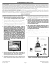
5. With the ignition still in the “on” position, adjust fuel pressure to the
desired level. Refer to the instructions provided with the fuel
pressure regulator for proper adjustment procedure. Continue to
check for leaks while adjusting the fuel pressure.
6. If desired static fuel pressure is achieved, and no leaks exist, turn off
power to the fuel pump, reinstall the fuel pump access cover and
rear seat (if removed for access).
7. Refer to the instructions provided with the fuel pressure regulator for
additional adjustment after starting the vehicle.
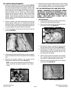
1. Make sure all connections are tight. Make sure the fuel supply and
fuel return hoses were not kinked or pinched during the remainder
of the installation, and tighten the fuel supply hose at the fuel pump,
and tighten the hose clamp on the fuel return hose at the fuel pump.
2. Check the overall fuel line routing, and using the provided tie-wraps,
secure the fuel lines away from any heat sources if necessary.
3. Reconnect the electrical connections to the fuel pump and fuel level
sender at the fuel tank. You may leave the access cover removed at
this time.
4. Reconnect the battery negative terminal. Turn the ignition or fuel
pump power switch to the “on” position, but do not start the vehicle.
Check for leaks. Refer to the “AFTER INSTALLATION, BEFORE
STARTING VEHICLE” section on page 1 for details. Remember to
enter your audio system security code if so equipped.
FINAL ASSEMBLY CHECKLIST
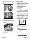
5. Make sure the fuel supply and return lines are routed into the engine
compartment towards the fuel filter and fuel pressure regulator. You
may now lower the vehicle and make the fuel line connections from
the top side.
6. Connect the fuel supply line to the inlet of the fuel filter.
6. Connect the fuel return line to the fuel pressure regulator.
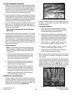
7. Connect the fuel filter using the previously built hose assembly to
the inlet side of the fuel rail
(See Fig. 18)
.
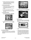
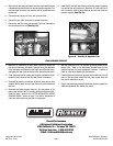
8. Install the 90° hose end side of the fuel rail to fuel pressure regulator
line onto the fuel rail’s outlet end. Attach the 45° hose end side of
this line onto the -6AN dry-sump fitting on the inlet side of the fuel
pressure regulator
(See Fig. 19)
.
Figure 18 - Fuel Rail Inlet
Figure 19 - Fuel Rail to Regulator Line
Russell Performance
A Division of Edelbrock Corporation
2700 California St. • Torrance, CA 90503
Toll-Free Tech-Line: 1-800-416-8628
E-Mail: Edelbrock@Edelbrock.com
®