


©
2007 Edelbrock Corporation
Brochure No. 63-641550
Catalog #641550
Rev. 10/07 - AJ/mc
Page 3 of 4
Fuel pressure regulator install
1. Find a safe and clean location in the engine compartment
for the placement of the fuel regulator and its mounting
bracket (supplied). In most applications, the best
placement for the regulator is on the firewall. Make sure
that the location will allow access for two hoses, entering
from the side and exiting from the bottom of the regulator.
Note:Some modification to the fuel pressure regulator bracket
may be needed for the correct fitment in your desired
location. Refer to the included fuel pressure regulator
instructions for details.
2. Following the instructions provided with the fuel pressure
regulator, mark and drill the mounting holes for the fuel
pressure regulator bracket.
3. Install 2 dry sump fittings (-6 AN) into the inlet and exit
ports of the regulator.
4. Install the -6 AN plug into the unused inlet port of the
regulator.
5. Install the vacuum hose from the regulator to the intake
manifold. It might be possible to use your stock vacuum
hose for the regulator depending on the placement of the
fuel pressure regulator.
6. Roughly install the fuel pressure regulator onto the vehicle
to facilitate hose assembly installation.
Russell fuel hose assembly and install
1. Attach the Russell EFI Ford fittings onto the factory supply
and return lines. This is accomplished by pushing the
proper fittings on to the factory lines until an audible click
is heard. Double check connections by tugging on the
fitting to ensure that the fitting is properly attached to the
factory hard line.
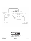
Note:Follow the included hose assembly instructions to properly
build the hose assemblies for the fuel system. Ensure that
the fuel hoses are properly located and installed so as to
prevent damage during the normal operation of the
vehicle. Please note that the instructions below give an
example of how this fuel system can be routed. It is highly
recommended that the installer pre-plan the routing of the
fuel system kit to determine which hose end fittings should
be used for each hose assembly.
2. Determine the hose path and length required for the fuel
hose leading from the EFI supply fitting to the fuel inlet
fitting located on the passenger side fuel rail. Build and
install the hose assembly.
3. Determine the hose path and length required for the fuel
hose leading from the passenger side fuel rail to the
driver side fuel rail inlet. Build and install the hose
assembly.
4. Determine the hose paths and lengths required for the
fuel hose leading from the exit of the driver’s side fuel
rail to the inlet of the fuel pressure regulator. Build and
install the hose assembly.
5. Determine the hose path and lengths required for the
fuel hose leading from the outlet of the regulator to the
EFI return side fitting. Build and install the hose
assembly.
6. Properly install the fuel pressure regulator to the chassis
at this time.
Final assembly checklist:
1. Make sure all connections are tight. Make sure the fuel
supply and return hoses were not kinked or pinched
during installation. Check for any interferences around
the fuel system hoses and fittings. The use of tie wraps
to secure the hoses is recommended.
2. Reconnect the negative battery terminal. Turn the
ignition or fuel pump power switch to the “on” position,
but do not start vehicle. Check for leaks.
3. With the ignition still in the “on” position, adjust the fuel
pressure to the desired level. Refer to the instructions
provided with the fuel pressure regulator for proper
adjustment procedures. Continue to check for leaks.
4. Refer to the instructions provided with the fuel pressure
regulator for additional adjustments after starting the
vehicle.