


©
2007 Edelbrock Corporation
Brochure No. 63-641550
Catalog #641550
Rev. 10/07 - AJ/mc
Page 2 of 4
BEFORE BEGINNING
Someone who has a basic knowledge of automobile repair and modification and is familiar with and comfortable with working on
their vehicle can accomplish the mechanical installation of this kit using common tools and procedures. However, this kit is designed
to allow you to custom fit the fuel lines and components to your application, and will require that you cut hoses to fit and drill holes
for fuel pressure regulator mounting, junction blocks, etc. If you do not feel comfortable with any of the steps listed below, please
consult a qualified professional installer. Make sure to read the instructions provided with the supplied fuel rail and fuel pressure
regulator. These will be referenced throughout this instruction sheet.
AFTER INSTALLATION, BEFORE STARTING THE VEHICLE ALWAYS make sure to check for any leaks BEFORE starting the vehicle.
Reconnect the battery and turn the ignition key to the “ON“ position. This will activate the fuel pump and pressurize the fuel
system. If any leaks are present, turn the ignition “OFF”, disconnect the battery, and make the necessary corrections before
continuing.
Stock fuel rail disassembly
1. Make sure the vehicle is on level ground, and the gear
selector is in park or 1st gear. Set the parking brake or
chock the wheels.
2. Make sure that the vehicle has cooled down.
3. Disconnect the negative terminal on the battery.
4. Thoroughly clean the area surrounding the fuel injectors
and the fuel rail. This will prevent debris from entering the
fuel system or the intake manifold upon fuel rail/injector
removal.
5. Relieve residual fuel pressure in the fuel system. Remove
the dust cap cover over the Schrader valve located on the
fuel tube leading to the rail. Hold a shop towel or rag
around the valve while relieving the fuel pressure to
prevent any fuel spray.
6. Using the EFI coupling release tool, disconnect the fuel
feed and return lines. Use a shop towel or rag to catch any
residual fuel remaining in the factory lines.
7. Remove the bolts holding the fuel rail to the intake
manifold.
8. Remove the fuel regulator, vacuum hose, fuel rail, and the
fuel injectors.
9. Inspect and replace the fuel injector o-rings if necessary.
10. You will also need to remove the remaining fuel hard tube
(feed and return) running from the fuel rail to the lower
firewall.
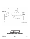
Russell (Manifold Kit) fuel rail install
1. Attach supplied brackets to the supplied fuel rails using
the supplied hardware. Use thread locking compound.
Note:
Install most of the necessary components onto the fuel
rail before installing in vehicle for ease of assembly. Be
sure to use thread sealing compound on NPT threads to
prevent leaks.
2. Using the supplied 3/8 NPT plug, install into the front end
of the driver’s side fuel rail. This end of the fuel rail will
be located behind the distributor.
3. Choose a suitable location on the fuel rails for a -3/8 NPT
male to -6 AN male pressure adapter to be installed.
Loosely install the -3/8 NPT male to -6 AN male pressure
adapter into the fuel rail. Mock up the fuel rail with the
pressure gauge installed on the fuel pressure adapter
fitting to check for clearances. After a suitable location
has been determined, correctly install the pressure
adapter fitting and the fuel pressure gauge.
4. Install the 3/8 NPT male to -6 AN male fittings into the
rest of the inlets and outlets of the fuel rails.
5. Depending on which intake manifold is used in
conjunction with this fuel system kit, the fuel rail spacers
(included) might need to be used to properly space the
driver’s side fuel rail from the intake manifold.
6. Mount the assembled fuel rails onto the intake manifold.
Careful attention should be paid to prevent any damage
to the injector o-rings during installation. Fasten the fuel
rails to the intake manifold using the supplied hardware
or the factory hardware.