


©
2007 Edelbrock Corporation
Brochure No. 63-641540
Catalog #641540
Rev. 10/07 - AJ/mc
Page 4 of 5
3. Connect other large (12 gauge) red relay wire to the
positive (+) battery terminal.
4. Connect small pink relay wire to a 12V switched (“key-
on”) power supply (e.g. terminal in a fuse box or splice
on ignition switch).
5. Connect black relay wire and black fuel pump lead wire
to a good chassis, engine, or battery ground.
Russell Profilter install:
1. Install two (2) -10 AN to -8 AN fittings into the Profilter.
Note the inlet and outlets of the fuel filter during the
installation.
2. Find a suitable location for the Profilter on the vehicle.
The location should allow for easy access to the fuel
filter to facilitate servicing in the future.
3. Install the fuel filter onto the vehicle using the supplied
bracket.
Russell Y-Block install:
1. Install the -10 AN to -8AN adapter fitting into the
bottom of the Y-block.
2. Install the -8 AN dry sump adapter fittings into the two
exit ports of the Y-block.
3. Install the fuel pressure gauge into the 1/8 NPT port
located on the front of the Y-block.
4. Find a suitable location for the Y-block on the vehicle. It
might be necessary to fabricate a custom mounting
bracket to install the Y-block. Mount the Y-block onto
the vehicle.
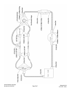
Russell fuel hose assembly and install:
Note:
Follow the included hose assembly instructions to
properly build the hose assemblies for the fuel system.
Ensure that the fuel hoses are properly located and
installed so as to prevent damage during normal
operation of the vehicle. Please note that the
instructions below give an example of how this fuel
system can be routed. It is highly recommended that
the installer pre-plan the routing of the fuel system kit
to determine which hose end fittings should be used for
each hose assembly. Use the supplied hose cushion
clamps to support the fuel hose as needed.
1. Determine the hose path and length required for the
fuel hose leading from the fuel tank outlet fitting (not
included) to the fuel inlet fitting of the fuel pump. Build
and install the hose assembly.
2. Determine the hose path and length required for the
fuel hose from the fuel pump to the fuel filter inlet. Build
and install the hose assembly.
3. Determine the hose paths and lengths required for the
fuel hose leading from the fuel filter outlet to the inlet
of the Y block. Build and install the hose assembly.
4. Determine the hose path and lengths required for the
fuel hose leading from the outlets of the Y-block to the
inlets of each of the fuel rails. Build and install the two
hose assemblies.
5. Determine the hose path and lengths required for the
fuel hoses leading from outlets of the fuel rails to the
inlets of the fuel pressure regulator. Build and install
the two hose assemblies.
6. Determine the hose path and lengths required for the
fuel hose leading from the fuel pressure regulator
outlet to the fuel tank inlet fitting (not included).
7. Properly install the fuel pressure regulator to the
chassis at this time.
Final assembly checklist:
1. Make sure all connections are tight. Make sure the fuel
supply and return hoses were not kinked or pinched
during installation. Check for any interferences around
the fuel system hoses and fittings. The use of tie wraps
to secure the hoses is recommended.
2. Reconnect the negative battery terminal. Turn the
ignition or fuel pump power switch to the “on” position,
but do not start vehicle. Check for leaks.
3. With the ignition still in the “on” position, adjust the fuel
pressure to the desired level. Refer to the instructions
provided with the fuel pressure regulator for proper
adjustment procedures. Continue to check for leaks.
4. Refer to the instructions provided with the fuel
pressure regulator for additional adjustments after
starting the vehicle.