


Catalog # 60219 - #60399
Rev. 3/09 - AJ/mc
Page 2 of 3
©2009 Edelbrock Corporation
Brochure #63-0009
Exhaust Headers: Any header or manifold designed for original equipment heads will fit the Edelbrock Street Cylinder Heads. Exhaust ports are
CNC-profiled to match Edelbrock #7227 or Fel-Pro #1415 exhaust gaskets, which are recommended for this application. For maximum
performance, the opening of exhaust header flange should match an Edelbrock #7227 or Fel-Pro #1415 gasket.
Spark Plugs: Use 14mm x 3/4" reach gasketed spark plugs. Heat range will vary by application from Champion RC9YC to Champion RC14YC.
The RC12YC is the plug used in the RPM applications (or equivalent). Use anti-seize on the plug threads to prevent galling in the cylinder
head, and torque to manufacturer's specification for aluminum heads.
Head Gaskets: Head gaskets requirements change according to the application for which the
cylinder heads are being used. Use the following as a guide for head gasket selection. NOTE: Certain
Ford SVO Performance blocks include additional blind cooling provisions on the exhaust side of the
deck surface. These holes may line up with a tooling point on the deck surface of the cylinder head
(identifiable as a rough low spot), which could prevent the head gasket from sealing properly. Using
the gasket as a template, verify that the head will compress the gasket above any such hole before
drilling. Use a small set-screw to block this passage if necessary, on blocks in which the hole has
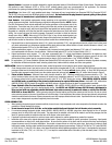
already been drilled. NOTE: When using Fel-Pro Print-O-Seal, or any silicone beaded gasket, you
must apply a small strip of silicone to both the deck flange of the cylinder head, as shown to the right,
and the same location on the surface of the block to prevent coolant from contaminating the oil.
1. Engines with low or stock compression ratios (8-10:1), stock size head bolts (7/16"), and applications where the cylinder head is being used
as a stock replacement or a performance upgrade with the stock piston volume, without nitrous or forced induction (blowers or turbos) - use
Edelbrock head gasket #7313 or Fel-Pro Head Gasket, #9333-PT1.
2. Medium performance engines, 10-12:1 compression ratio, increased pre-load cylinder head fasteners (7/16" stud or ½" head bolts or studs),
not recommended with nitrous or forced induction - Edelbrock head gasket #7313 or Fel-Pro Head Gasket, #1011-2.
3. Highest performance racing engines. 12:1 and above compression ratio, ½" cylinder head fasteners designed for the highest pre-load,
engines using nitrous or forced induction - Fel-Pro Head Gasket #1006 Locwire. NOTE: This gasket will require a groove to be cut in the
deck surface of the cylinder head by a competent machine shop to Fel-Pro specifications. See “OTHER ASSEMBLY TIPS:” below.
NOTE: For applications 1 & 2 above, Edelbrock Cylinder Head Gasket Set #7364 may also be used. This gasket set includes all gaskets necessary
for installation of Edelbrock cylinder heads, including cylinder head, intake manifold, exhaust, and valve cover gaskets.
INSTALLATION: Before final installation of the cylinder heads, several things need to be checked to assure proper engine operation:
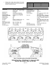
1. Check the upper deck to see if you have an early or late model block (not needed with 351-W): a) Late model 289-302 blocks have the water
passages located next to the head bolt location on the deck of the block (This block will not
require drilling). b) Early 289-302 blocks will
have the water passages located directly over the cylinder upper deck area and will require drilling 1/8" steam holes as seen in Figure 2.
2. Piston to Valve Clearance - Minimum intake valve clearance should be .080". Minimum exhaust valve clearance should be .110". The
point of minimum intake valve to piston clearance will usually occur somewhere between 5° and 20° ATDC during valve overlap. The point
of minimum exhaust valve to piston clearance will usually occur 20° to 5° BTDC during valve overlap. With #60259, #602579, #60359
and #60399 heads, re-machining of the piston top eyebrows may be required with some pistons. Heads with 1.90" intake valves
(#60229, 60329, & 60379) should be compatible with stock pistons in engines that have the stock or recommended camshafts.
3. Proper Hydraulic Lifter Pre-Load and Rocker Geometry - With #60229, #60259, #60329 and #60359 cylinder heads, hydraulic lifter
pre-load is easily adjustable due to the stud/guideplate design. On #60379 and #60399 Performer 5.0/5.8L heads, adjustments to
lifter pre-load with non-adjustable pedestal bolt-down style rockers can only be made with shims as sold by Ford SVO #M-
6529-A302 or Crane #99170-1. Rocker geometry should be checked making sure that the contact point of the roller or pad on a stock
rocker remains properly on the valve tip and does not roll off the edge. Visual inspection of the rockers, valve springs, retainers, and pushrods
should be made to ensure that none of these components come into improper contact with each other. If problems with valve train geometry
occur, simple changes such as pushrod length may have to be made.
OTHER ASSEMBLY TIPS:
• When installing the sparkplugs and exhaust manifolds, be sure to use a high temperature anti-seize compound on the threads to reduce the
possibility of thread damage in the future.
• Do not exceed a torque of 16-18 ft./lbs. on the intake manifold bolts and lubricate the bolt threads prior to assembly.
• For emissions passage equipped cylinder heads (#60329, #60359, #60379, & #60399), plugs have been supplied for the air injection
passage, which is drilled in the end of the heads. The plugs should be installed in the front of the heads to seal off the passages, and the
stock air injection manifold is installed on the back of the engine in the stock location.
• If pushrod to cylinder head contact is a problem, loosen rocker studs and re-position guideplate as needed for clearance.
• Installation is the same as for original equipment cylinder heads. Consult service manual for specific procedures, if necessary. Head gasket
recommendations are listed in the head gasket section. Be sure that the surface of the block and the surface of the head are thoroughly
cleaned to remove any oily film before installation. Use alcohol or lacquer thinner on a lint-free rag to clean. Apply moly-oil mixture to head
bolt threads, washer, and area under head bolt to prevent galling and improper torque readings. Torque to 70 ft./lbs. for 7/16" bolts (289/302)
or 100 ft./lbs. for ½" bolts (351-W) in three or four steps following the factory tightening sequence (see Figure 1), then tighten the long (upper)
head bolts to 80 ft./lbs. (7/16") or 110 ft./lbs. (1/2"). A re-torque is recommended after initial start-up and cool-down (allow 2-3 hours for
adequate cooling).