


Catalog #2281
Rev. 4/07 - RS/mc
©2007 Edelbrock Corporation
Brochure #63-2281Page 3 of 4
INSTALLATION PROCEDURE
1. Check lifters as covered in Lifters section. Coat cam lobes with
fresh clean oil. Lube distributor drive of cam with assembly lube
(supplied).
2. Install new camshaft and factory thrust plate. Torque thrust plate
bolts to 9-12 ft./lbs. Install new sprockets and timing chain. Torque
cam sprocket bolts to 40-45 ft/lbs.
CAUTION: When using an Edelbrock Timing Chain and Gear
Set with an Edelbrock cam, straight up timing alignment is
achieved. If any other timing gear set is used, it is necessary
to check camshaft position for correct timing alignment. This
requires indexing the camshaft with a degree wheel to verify
timing alignment. O.E.M. or non-Edelbrock timing gear sets are
not recommended for use with Edelbrock camshafts. Use
locking compound material on bolts holding gear to cam.
3. Install your roller lifters using fresh clean oil on the lifter and the
lifter bore just prior to installing. Check to make sure all lifters fit
freely in lifter bores.
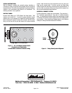
4. Align camshaft with timing marks lined up as recommended by
factory specifications. See Figure 2.
5. Torque front timing cover bolts to 12-18 ft. lbs., and tighten oil pan
bolts.
NOTE: Install new seal between oil pan and front cover if old
seal was damaged upon removal. Use RTV silicone sealant on
seal to ensure proper seal to pan.
6. Install front harmonic balancer and torque to 70-90 ft.-lbs.
7. Install fuel pump.
8. Install water pump using new gaskets and torque to 30 ft.-lbs.
9. VALVE ADJUSTMENT
A. Install pushrods with lube on both ends, making sure the
pushrod tip hits the center of the lifter cup. Install rocker
arms, but do not install adjusting nuts. You are now ready
to start valve adjustment.
B. Turn the engine over until the No. 1 cylinder exhaust lifter
just starts to move up. At this point, install adjusting nut on
the intake rocker arm and adjust to zero clearance between
rocker arm and valve tip. This is “zero lash”. While
tightening the rocker nut, spin the pushrod between your
thumb and forefinger. When you feel resistance, you are at
zero lash. From this point turn adjusting nut down (clock-
wise) 3/4 turn more for final adjustment.
C. Turn the engine over again until the intake lifter just stops
coming down. Install the adjusting nut on the exhaust
rocker arm and adjust to zero clearance between rocker
arm and valve tip. From this point turn adjusting nut down
(clock-wise) 3/4 turn more for final adjustment.
D. The above procedure assures correct hydraulic lifter
preload. Repeat this procedure for each of the other seven
cylinders.
10. Install intake manifold using new intake gasket set and torque bolts
to 25 ft/lbs.
DISTRIBUTOR INSTALLATION & ENGINE TIMING:
NOTE: This cam is a cast cam and requires a cast distributor drive
gear.
1. Turn the engine over in direction of rotation until the No. 1 intake
valve closes and continue until the pointer on the front cover is
approximately five degrees before top dead center (BTDC).
See
Figure 1
for firing order.
2. Re-install the distributor with the rotor pointing towards No. 1
terminal in the cap, and with the distributor housing in its original
position. If distributor will not drop down all the way to the flange
on the manifold, it will be necessary to align the distributor shaft
with the oil pump drive. Slowly rotate the engine until the distributor
drops down against the manifold, then continue turning until two
complete revolutions are completed and the timing marks once
again come to five degrees BTDC.
3. Lightly tighten the hold-down clamp so that the distributor can still
be turned to determine final setting using a timing light with the
engine running.
4. Replace valve covers, carburetor linkage and remaining vacuum and
electrical connections.
5. Engine oil and filter should be changed before start-up.
CAMSHAFT & LIFTER RUN-IN:
IMPORTANT: Standard camshaft run-in is not required when using
a roller cam.
11. Remove rocker arms and pushrods.
12. Remove hydraulic valve lifters.
13. Remove crankshaft pulley, and using a suitable puller, remove the
crankshaft dampener.
14. Remove fuel pump. Rotate engine until timing marks are aligned
(See Fig. 2)
.
15. Loosen oil pan and remove water pump and front cover.
NOTE: The front cover oil seal should be replaced before the
front cover is re-installed.
16. Remove bolts retaining camshaft sprocket. Remove sprocket and
chain. Using a suitable puller, remove the crankshaft sprocket.
17. Remove thrust plate and camshaft,being careful not to damage cam
bearings. Cam bearings should be replaced if necessary.