


Catalog #2281
Rev. 4/07 - RS/mc
©2007 Edelbrock Corporation
Brochure #63-2281Page 2 of 4
REMOVAL OF ENGINE PARTS BEFORE CAMSHAFT INSTALLATION
(Be sure to keep all parts in order)
WARNING! DO NOT REMOVE RADIATOR CAP OR RADIATOR HOSES WHILE ENGINE IS HOT!
IMPORTANT NOTICE: If the air conditioning condenser needs to be removed to provide clearance for camshaft removal, have the system
evacuated by an appropriate repair facility BEFORE starting the installation. The facility can recharge the system after installation.
1. Disconnect the battery.
2. Drain radiator coolant. Drain plug will normally be located on lower
right or left side of the radiator facing the engine.
3. Remove radiator and air conditioning condenser, if so equipped. In
some cases, the front grille may have to be removed. Measure
distance from front cover to grille or brackets that may interfere with
camshaft against the length of the camshaft.
4. Remove the gas cap to relieve pressure. Disconnect fuel line and
plug. Replace gas cap.
5. Disconnect all linkage from carburetor such as throttle, throttle
springs, transmission, cruise control and automatic choke.
6. Tag and remove coil wires and sensor wires.
7. Tag and remove vacuum lines.
8. Remove valve covers.
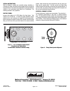
9. Remove distributor cap and wires, rotate engine until rotor points
towards number 1 terminal in cap and pointer on front cover is on
top dead center (TDC) and remove distributor
(See Fig. 1)
.
NOTE: Mark the approximate position of the distributor
housing in relation to the manifold to assist in getting the
distributor properly located during re-installation.
10. Remove carburetor and intake manifold. Remove and discard intake
manifold gasket. Clean addisional gasket material and sealant from
the cylinder head flanges. Cover the lifter valley with rags and use
care to prevent material from falling into the lifter valley.
IMPORTANT NOTES AFFECTING YOUR WARRANTY.
PLEASE READ BEFORE CONTINUING THIS INSTALLATION!
CAM LOBE DAMAGE: Cam lobe wear is almost non-existent unless
mismatched parts are used or installation of the cam and lifters is done
improperly. Cam damage can result from the timing gear loosening due
to improper torque on bolts. Bolts holding gear to camshaft should be
torqued carefully and a locking compound applied to threads of bolts.
Before installing your new Performer-RPM roller camshaft, check the
gear drive on the distributor and oil pump for any signs of wear. If worn,
be sure to replace with a new gear or you may wear out your camshaft
prematurely. High-pressure oil pumps are not recommended with
Performer RPM roller camshafts. Edelbrock camshafts are designed to
be used with Edelbrock timing chains.
VALVE SPRINGS (CAUTION REGARDING YOUR WARRANTY):
In order for this Performer RPM roller cam to be covered under ANY
WARRANTY,you MUST use the correct Valve Springs. Failure to install the
correct valve springs may cause lifters not to follow the cam lobes and
damage engine parts. This camshaft is designed to function with valve
Springs that have a closed pressure of 110-120lbs, open pressure of
330-340 lbs and a lift of .600”. Special high performance retainers may
be necessary with your installation for proper spring height. Do not use
rotator type valve springs or retainers for this application.
Note: Edelbrock Sure Seat Valve Springs #5722 are not
recommended with cast iron heads.
LIFTERS: Edelbrock offers a replacement roller lifter kit, part #97453.
To install new or factory roller lifters, use fresh clean oil on the lifter and
the lifter bore just prior to installing. Make sure to re-install the factory
guide system (if applicable). The guide bar (high side of tappet) must
face the opposite side of block, with the arrow pointing up.
PUSHRODS AND ROCKER ARMS: High performance pushrods and
stud mounted, adjustable roller rocker arms are recommended for this
installation. Edelbrock Pushrods #9656 are recommended. After the
cam is installed and timed correctly
(See Figure 2)
, it will be necessary
to check each pushrod for correct lifter preload. Use lifter manufacturer’s
specifications for proper preload.
TIMING CHAIN: Use Edelbrock Performer-Link Timing Set #7811 or
7820, Hex-A-Just Timing Set #7335, or Accu-Drive Gear Drive #7892
ONLY (See catalog for application coverage). Do not use late model
timing chain and gear sets that are designed for emission-controlled
engines. These timing sets are machined in a retarded position and are
not recommended for this camshaft installation. Edelbrock Timing Sets
feature adjustments to allow for specific timing selection.
CAM GEARS AND CAMSHAFT END PLAY: If cam gear becomes
loose, the cam will slide back in the block, causing the lifters to hit the
lobes next to them and also the cam bearing journals. If the engine is run
after this happens, the bottom of the lifters and the sides of the lobes will
become damaged. See Installation Instructions section for end play
specifications.
OPERATING CLEARANCES: When installing a camshaft, it is always
important to check for proper operating clearances, especially when high
performance components are used. Things to look for that can cause
failure and damaged parts are as follows:
1. Improper valve-to-piston clearance (this should be no less than
.080" for the intake valve, and .100” for the exhaust valve).
2. Rocker arm stud slot clearance (both ends; valve closed and
open).
NOTE: We recommend the use of roller rockers.
3. Proper spring settings (see dimensions with spring instruction
sheet). Correct dimensions mean maximum performance and
longer engine life.