


©2007 Edelbrock Corporation
Brochure #63-16045 of 6
Catalog #1604, 1606, 1607, 1624, 16041 & 16061
Rev. 3/07 - RS/mc
PUSH ROD INSTALLATION
1. Rotate the engine so that both lifters of the cylinder being serviced
are on the base circle (lowest position) of the camshaft.
NOTE: When using an aftermarket performance camshaft,
such as Performer RPM, which is dyno matched and
recommended for use with Performer RPM Cylyinder Heads,
you must use an adjustable pushrod kit such as Edelbrock
#1737. Refer to the instructions provided with your pushrod
kit for the proper valve adjustment procedure. Complete this
adjustment procedure BEFORE performing the final pushrod
installation.
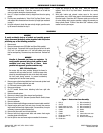
2. Refer to
Figure 1
. Install push rod covers and associated parts,
using new O-rings. Install push rods.
NOTE: Be sure to use new O-rings on push rod tubes to
prevent leaks. Also check carefully to be certain old O-rings
were removed from push rod tubes and lifter bores.
3. Install gaskets (15 and 16). Place lower rocker box assemblies (17;
with rocker arms and shafts) in position.
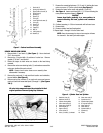
NOTE: Rocker arm shafts are notched to accept the rocker
arm retaining bolts. Align the notches with the bolt holes
before installing the bolts (See Figure 10).
3. Cylinder Head bolt torque sequence
(See Figure 8)
:
The procedure for tightening the head bolts is extremely critical; not
only to prevent gasket leaks, but to prevent stud failure and heads
and cylinders distortion.
CAUTION
Be sure you thoroughly clean and lubricate the
cylinder head bolts before tightening to the correct
torque. Friction because of dirt or grime will cause
the torque wrench readings to be incorrect. Clean
and lubricate the threads with engine oil and screw
the bolts onto the crankcase studs by hand to be sure
there is no friction.
A. Cylinder Head Torque Sequence for 1984-85 Models
CAUTION
Use only original equipment head bolts and studs
for your year vehicle to ensure proper torque and
head gasket life.
1.
See Figure 8
. With a torque wrench, start at the
cylinder head bolt numbered "1" and tighten to 7-9
ft./lbs. Then tighten "2", "3", and "4" in order to 7-9
ft./lbs.
2. Following the torque sequence, tighten each bolt to
15-17 ft./lbs.
3. Following the torque sequence, tighten each bolt to
24-26 ft./lbs.
CAUTION
The cylinder head bolts are not
to be checked
for tightness after final torquing at reassembly
is completed. Retightening the bolts to
specified torque at regular intervals will place
undue stress on bolts and bolt anchoring
threads.
B. Cylinder Head Torque Sequence for 1986-95 Models
CAUTION
Use only original equipment head bolts and studs
for your year vehicle to ensure proper torque and
head gasket life.
1.
See Figure 8
. With a torque wrench, start at the
cylinder head bolt numbered "1" and tighten to 7-9
ft./lbs. Then tighten "2", "3", and "4" in order to 7-9
ft./lbs.
2. Following the torque sequence, tighten each bolt to
12-14 ft./lbs.
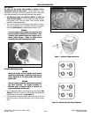
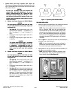
3.
See Figure 9
. Mark a line on the cylinder head and
a corresponding line on the head of the cylinder head
bolt as shown in View A. Following the same
sequence 1, 2, 3, then 4, turn each bolt, one at a time
one quarter turn (90°) using the marks as a guide.
When marks are all positioned, as in View B, the
procedure is completed.
Figure 9 - Tightening 1986-1995 Head Bolts
Figure 10 - Rocker Arm Shaft Bolt Notches