


6
Edelbrock Performer Series Carburetor Owner’s Manual 8/94
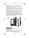
TRANSIENT CONTROL SYSTEMS
In addition to the three (3) basic Metering Systems, there are two (2) Transient Control Systems; The
Secondary Auxiliary System and The Pump System.
Secondary Auxiliary System
During the initial stages of Secondary Operation, the air flow rate through the secondaries is very low.
Accordingly, there is not enough pressure drop (suction) at the Secondary Nozzle to induce fuel flow.
In order to prevent a lean A/F condition that would be experienced by the driver as a
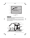
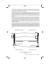
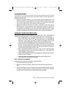
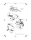
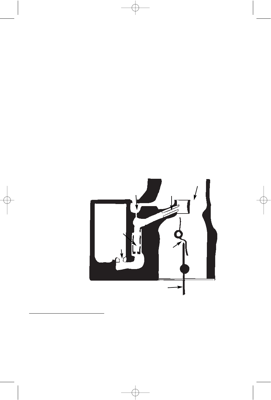
Secondary Main System: The Secondary Main System (Figure 5) delivers fuel only when the
secondary throttle blades and air valve are open. It ensures that fuel delivery varies with air flow.
The Secondary Throttles (1) begin to open when the Primaries are about 65% open. The Primary and
Secondary Throttles arrive at the WOT stop at the same time.
Air flow through the Secondary side is controlled by Air Valves (2). These valves are located in the
secondary bores above the throttle blades. They are balanced against a counter weight and open to
admit additional air flow only if there is enough air velocity to allow the proper operation of the
Secondary Metering Systems.
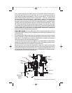
The principles of operation for the Secondary Main System are the same as those that govern the
operation of the Primary Main System; the pressure drop (suction) arises from the increase in the airs
velocity as it passes through the Venturi sections. The pressure drop (suction) at the Secondary
Booster Venturi (3) is communicated into the system by the Secondary Nozzle (4).
Fuel flows through the Secondary Main Jet (5) to the Secondary Well where it is drawn through the
Secondary Well Tube (6). The fuel is mixed with air that enters the tube through a series of small
holes. The source of the air is one of the Secondary Well Bleeds (7). There are two air-bleeds; one
admits air to the outside of the Well Tube and the other allows air to flow into the passage behind the
Nozzle. The fuel, now well mixed with air, flows through the slightly up-hill passage and exits into the
Secondary Boost Venturi (3) through the Secondary Nozzle (4).
Secondary Main
Systems
Figure 5
(6) Secondary
Well Tube
(7) Secondary
Well Bleeds
(2 bleeds)
(4) Secondary
Nozzle
(3) Secondary
Boost
Venturi
(2) Air
Valve
(5) Secondary
Main Jet
(1) Secondary
Throttle
1403-1413 Perf Series Carburetor Owner's Manual.qxd 3/31/2006 12:10 PM Page 6