


14
Edelbrock Performer Series Carburetor Owner’s Manual 1/01
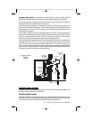
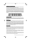
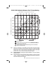
CALIBRATING THE POWER MODE STAGING
The Step-Up function, which moves the Metering Rod to the Power Mode, is controlled by the Step-Up
Spring. The base calibration has a spring which “stages” rich at 5” Hg.
If your vehicle has a mid-throttle driveability problem that is encountered as the throttle is gradually
opened, but then goes away upon further opening, it may be possible to eliminate the lean spot by
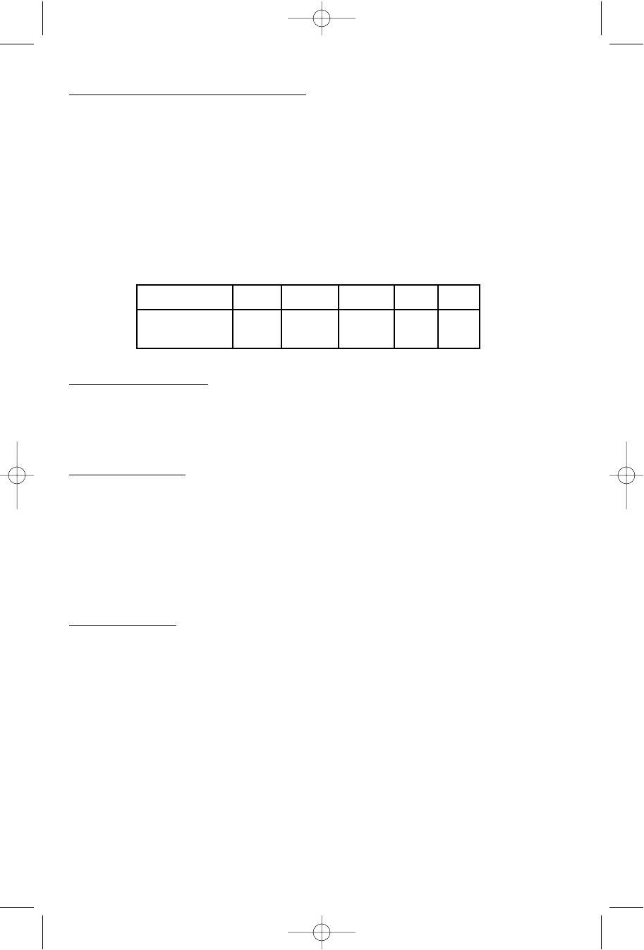
using a stronger Step-Up Spring. The available Step-Up Springs are listed in the following chart along
with their respective “staging” point. It is best to select a new spring on the basis of vacuum
readings, but in the absence of a gauge, try the strongest spring (highest vacuum rating) to see if the
problem goes away. If the drive problem is cured by the strong spring, try the next weakest spring as
well. If the strong one does not help, then the calibration problem is related to the A/F metering stage
of either the Cruise or Power Modes. Use the Calibration Reference Chart to help select another
combination.
CALIBRATING THE PUMP
If you encounter any hesitations or stumbles that do not seem to be related to the basic metering or
have not responded to changes in the basic metering, move the pump drive link to one of the holes
closer to the carburetor body. This will increase the stroke length of the plunger and result in more
pump delivery.
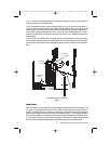
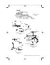
FLOAT ADJUSTMENT
To properly adjust the floats in the EPS carburetor, two procedures must be followed. First, invert the
airhorn cover (Figure 8) holding the airhorn gasket in place. There should be 7/16” between the
airhorn gasket and the top of the outer end of the float. To adjust the float level, bend the float lever
until the recommended level is attained. DO NOT press the needle into the seat when adjusting the
float lever. Next, you should check the float drop (Figure 9). Hold the airhorn upright and let the floats
hang down. There should be 15/16" to 1" between the airhorn gasket and the top of the outer end of
the float. To adjust the float drop, bend the tab on the back until the recommended float drop is
attained. For the off-road float adjustment, see page 16.
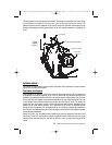
CHOKE ADJUSTMENT
To adjust the choke piston linkage (Figure 10) open the choke valve and insert a .026” wire, with a 90
degree bend 1/8” from the end, between the top of the slot in the choke piston cylinder and the
bottom of the slot in the piston. Hold the wire in position and close the choke valve by pressing on
piston lever A until resistance is felt. The dimension C should be .100” between the top edge of the
choke valve and the air horn. To adjust, bend rod B.
To adjust the fast idle linkage (Figure 11) place the fast idle screw A between the two notches on the
cam. Close the choke valve as far as possible without forcing it. The dimension C should be 3/64”
between the choke valve and the air horn. To adjust bend rod D.
Fast idle may be adjusted to manufacturers specifications (usually 1500 rpm) during normal choke
cold operation. The fast idle screw A can be adjusted with engine off and throttle held open to allow
screw head access. Recheck fast idle speed after each adjustment.
Spring Color Blue Yellow Orange Pink Plain
Staging Vacuum 3" 4" 5" 7" 8"
("Hg)
A complete set of these springs is available separately as Edelbrock part #1464.
1403-1413 Perf Series Carburetor Owner's Manual.qxd 3/31/2006 12:10 PM Page 14