


4
Edelbrock Performer Series Carburetor Owner’s Manual 8/94
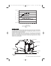
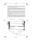
Fuel is drawn through the Idle System (Figure 2) by the intake manifold vacuum that is
communicated at the Idle Screw Port (8) and Transfer Slot (7). Fuel in the bowl passes through the
Primary Main Jet and Metering Rod Restriction (1) and into the Primary Well (2). The fuel for the Idle
System is drawn through the restriction at the end of the Idle Jet (3) - a brass tube - and flows up the
tube to the location of the 1st Idle Air Bleed (4) - a brass restrictor - where air is mixed with the liquid
fuel. The emulsified air and fuel is then drawn through the Idle Channel Restrictor (5) - a drilled passage
that serves to increase the velocity of the air and fuel to promote better mixing. As the emulsified fuel is
discharged from the Idle Channel Restrictor, additional air is added at the 2nd Idle Air Bleed (6) - a drilled
hole - and the highly aerated mixture then moves through the passages in the main-body to the location
of the Transfer Slot (7) and Idle Screw Port (8). The Transfer Slot (7) is a large air bleed when the throttle
is closed, but as the throttle is opened the slot is exposed to manifold vacuum and becomes a discharge
port for Idle System fuel. The Idle Screw Port is a variable discharge restriction that is adjusted by the
engine tuner to achieve the desired A/F Ratio at engine idle.
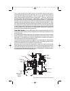
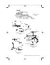
Primary Main System: The Primary Main system delivers an increasing percentage of the fuel as
throttle position increases (phasing over the Idle System) and varies fuel delivery in response to air flow
and manifold vacuum.
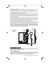
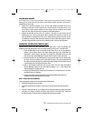
Fuel is drawn through the Main System (Figure 3) by the pressure-drop that occurs when the incoming
air flow must increase in velocity in order to pass the reduced throat areas at the Main Venturi (1) and the
Boost Venturi (2). This pressure-drop (or suction) is communicated to the system by the Nozzle (3)-a
brass tube that opens into the inside of the Booster Venturi (2).
The fuel must pass through the restriction at the Main Jet (4) and Metering Rod (5). The Rod extends
through the Jet, reducing the amount of area available for fuel flow. If the diameter of the Rod is large,
then fuel flow through the Jet is more restricted than if the Rod were small.
After the Rod and Jet, the fuel enters the Primary Well and is drawn up the inside of the Primary Well
Tube (6). Sometimes this tube is called an Emulsion Tube. Here, the fuel is mixed with air that enters the
inside of the Tube through a series of small holes. The air is supplied by the Main Well Bleed (7) at the
top of the Main Well. The air/fuel mixture exits from the top of the Main Well into a passage that leads it
to discharge into the Booster Venturi (2) at the Nozzle (3).
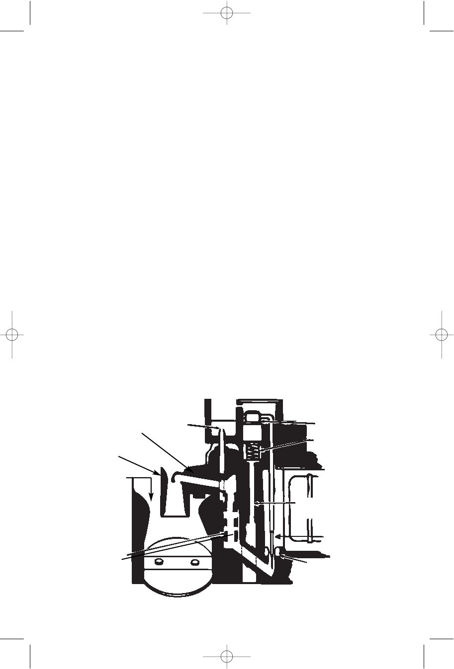
Primary Main
System
Figure 3
(6) Primary
Well
Tube
(1) Main
Venturi
(2) Boost
Venturi
(3) Nozzle
(7) Main
Well
Bleed
(9) Step-Up
Piston
(8) Vacuum
Passage
(5) Metering Rod
(4) Main Jet (primary)
(10) Step-Up
Piston Spring
1403-1413 Perf Series Carburetor Owner's Manual.qxd 3/31/2006 12:10 PM Page 4