5
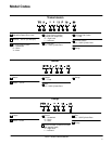
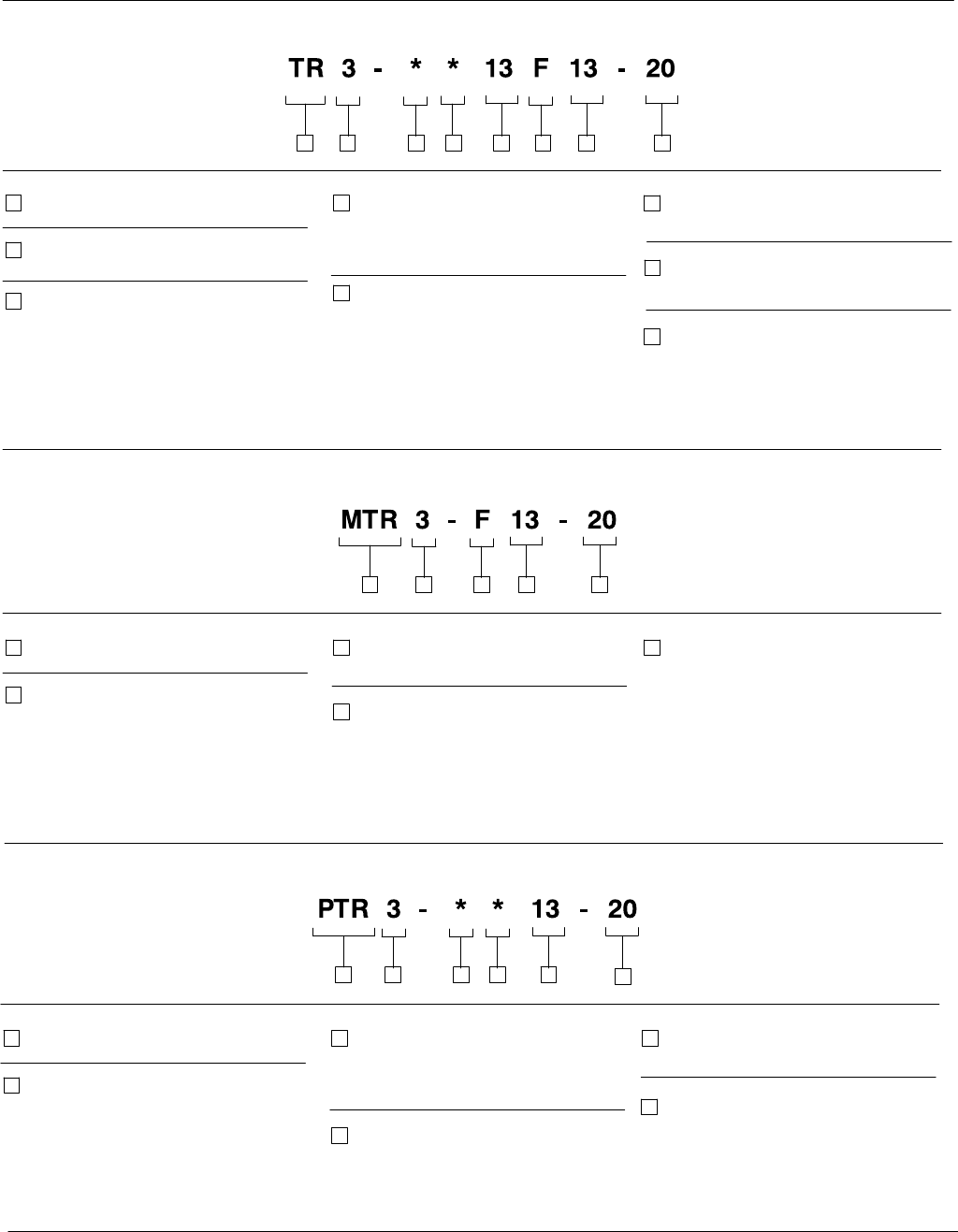
Model Codes
Control
F – Fixed
Control
H – Handwheel
D – Servo
V – None
“A” End Control Location
(viewed from output end)
R – Right hand
L – Left hand
1
3 46 871 2
2
3
6
7
Adjustable Speed Drive Units
Nominal – 3/4 HP (at 1200 rpm)
“A” End (Pump) Control
H – Handwheel
D – Servo
V – None
“B” End Control
13 – 13/32 Cylinder Bore
“B” Fixed End Control
F – Fixed
Table 1. Model Code Breakdown
4
Design
5
5
“A” End Size
13 – 13/32 Cylinder Bore
Transmission
8
Motor
3 41 2 5
1
2
Motors
Series – 3/4 HP
Design
Size
13 – 13/32 Cylinder Bore
4
3 5
Pump
3 41 2 5
1
2
Pumps
Series – 3/4 HP
Design
Control Location (viewed from shaft
end opposite shaft)
R – Right hand
L – Left hand
4
3 5
6
6
Size
13 – 13/32 Cylinder Bore


