


5
If any parts must be pressed from a shaft or from the
output hub, this should be done before ordering parts to
make sure that none of the bearings or other parts are
damaged in removal. Do not press against outer race of
any bearing.
Because old shaft oil seals may be damaged in
disassembly, it is advisable to order replacements for
these parts.
Removing Reducer from Shaft
CAUTION: Remove all external loads from drive before
removing or servicing drive or accessories.
WARNING: To ensure that drive is not unexpectedly
started, turn off and lock out or tag power source before
proceeding. Failure to observe these precautions could
result in bodily injury.
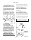
Straight Bore: Loosen screws in both output hub collars.
Remove the collar next to the end of the shaft. This
exposes three puller holes in the output hub to permit the
use of a wheel puller. In removing the reducer from the
shaft, be careful not to damage the ends of the hub.
Taper Bushed:
1. Remove bushing screws.
2. Place the screws in the threaded holes provided in
the bushing flanges. Tighten the screws alternately and
evenly until the bushings are free on the shaft. For ease of
tightening screws, make sure screw threads and threaded
holes in bushing flanges are clean.
3. Remove the outside bushing, the reducer, and then
the inboard bushing.
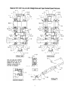
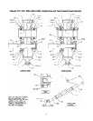
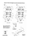
Disassembly:
1. Position the reducer on its side and remove all
housing bolts. Drive dowel pins from housing. Gently tap
the output hub and input shaft with a soft hammer
(rawhide, not a lead hammer) to separate the housing
halves. Open housing evenly to prevent damage to the
parts inside.
2. Lift shaft, gear, and bearing assemblies from
housing.
3. Remove seals from housing.
Reassembly:
1. Output Hub Assembly: Heat gear to 325°F to 350°F
to shrink onto hub. Heat bearings to 270°F to 290°F to
shrink onto hub. Any injury to the hub surfaces where the
oil seals rub will cause leakage, making it necessary to
use a new hub.
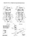
2. Countershaft Assembly: Shaft and pinion are integral.
Press gear and bearings on shaft. Press against inner (not
outer) race of bearings.
3. Input Shaft Assembly: Shaft and pinion are integral.
Press bearings on shaft. Press against inner (not outer)
race of bearings.
4. Drive the two dowel pins into place in the right-hand
housing half. Apply RTV732 sealant to carriers for R.H.
side(backstop side) of reducer. Install carriers and torque
bolts per table 4.
5. Place R.H. housing half on blocks to allow for
protruding end of output hub.
6. Install bearing cups in right-hand housing half,
making sure they are properly seated.
7. Mesh output hub gear and small countershaft gear
together and set in place in housing. Set input shaft
assembly in place in the housing. Make sure bearing
rollers (cones) are properly seated in their cups. set
bearing cups for left-hand housing half in place on their
rollers.
8. Clean housing flange surfaces on both halves,
making sure not to nick or scratch flange face. Place a
1/8 bead of RTV732 sealant on flange face. (make sure
RTV is placed between bolt holes and inside of flange
face) Place other housing half into position and tap with a
soft hammer (rawhide, not lead hammer) until housing
bolts can be used to draw housing halves together.
Torque housing bolts per torque values listed in table 4.
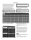
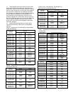
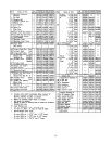
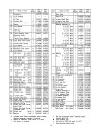
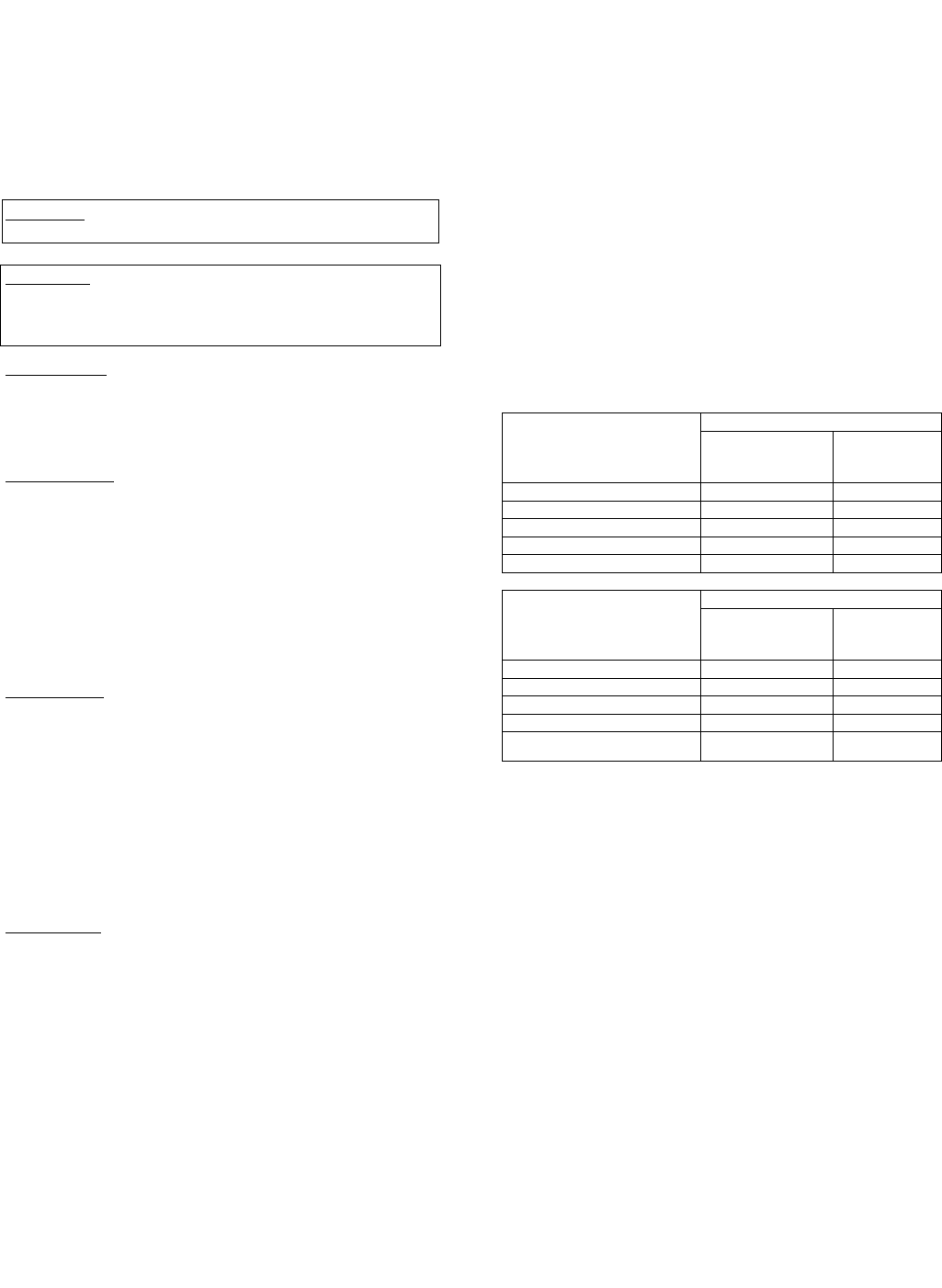
Table 4 – Recommended Torque Values
Dry Torque (lb.–ft.)
Reducer
Size
Housing
Bolts
Output Hub
Seal Carrier
Screws
TXT / HXT 305A & 3A 50–45 17–15
TXT / HXT 405A & 4A 50–45 30–27
TXT / HXT 505A & 5B 75–68 30–27
TXT605 & TXT / HXT 6 75–68 30–27
TXT705 & TXT / HXT 7 150–135 50–45
Dry Torque (lb.–ft.)
Reducer
Size
C’shaft
Bearing Cover
Screws
Input Shaft
Seal Carrier
Screws
TXT / HXT 305A & 3A 17–15 17–15
TXT / HXT 405A & 4A 30–27 30–27
TXT / HXT 505A & 5B 30–27 30–27
TXT605 & TXT / HXT 6 30–27 30–27
TXT705 & TXT / HXT 7
50–45 50–45
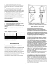
9. Place output hub seal carrier in position without
shims and install two carrier screws diametrically opposed.
Torque each screw to 25 in.-lbs. Rotate the output hub to
roll in the bearings and then torque each screw to 50 in.-
lbs. Again turn output hub to roll in the bearings. With a
feeler or taper gage, measure the gap between the
housing and the carrier flange. To determine the required
shim thickness, take the average of the two feeler gage
readings. Remove carrier and install the required shims
plus .002. Install carrier with shims and torque bolts per
table 4. Rotate hub assy, tap lightly with rawhide mallet on
end of hub, while rotating, to ensure bearings are seated.
Using a dial indicator check end play of hub bearings,
endplay should be .001-.003. Repeat this process as
necessary to obtain proper end play. Place a 1/8 diameter
bead of RTV732 sealant inside the carrier at the shim I.D.
and install carrier on reducer housing. Torque carrier bolts
to value shown in Table 4.
10. Adjust the countershaft bearings using the same
method as in step 8 above. The axial end play should be
.001” to .003”.
11. Again, using the same procedure as in step 8,
adjust the input shaft bearings, except the axial end play
should be .002” to .004”.