


2
INSTALLATION
1. Use eyebolts or lifting lugs to lift reducer.
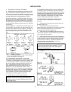
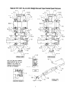
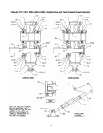
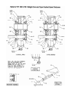
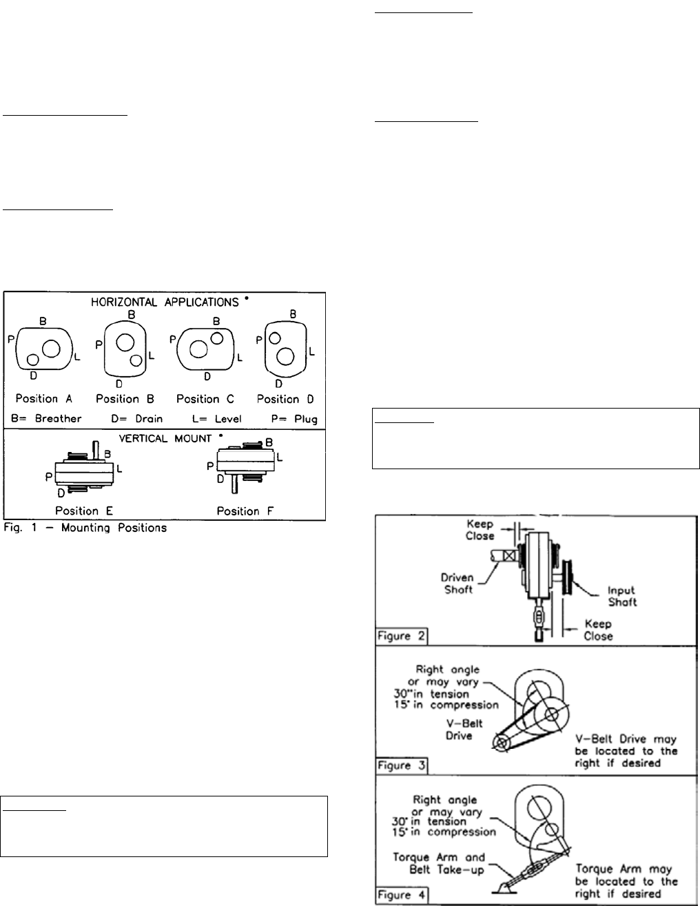
2. Determine the running positions of the reducer. (See
Fig. 1) Note that the reducer is supplied with either 4 or 7
plugs; 4 around the sides for horizontal installations and 1
on each face for vertical installations. These plugs must be
arranged relative to the running positions as follows:
Horizontal Installations - Install the magnetic drain plug in
the hole closest to the bottom of the reducer. Throw away
the tape that covers the filter/ventilation plug in shipment
and install plug in topmost hole. Of the 3 remaining plugs
on the sides of the reducer, the lowest one is the minimum
oil level plug.
Vertical Installations - Install the filter/ventilation plug in the
hole provided in the top face of the reducer housing. Use
the hole in the bottom face for the magnetic drain plug. Of
the 5 remaining holes on the sides of the reducer, use a
plug in the upper housing half for the minimum oil level
plug.
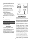
• Below 15 RPM output speed, oil level must be adjusted
to reach the highest oil level plug (P.).
The running position of the reducer in a horizontal
application is not limited to the four positions shown in Fig.
1. However, if running position is over 20* in position "B" &
"D" or 5* in position "A" & "C", either way from sketches,
the oil level plug cannot be used safely to check the oil
level, unless during the checking, the torque arm is
disconnected and the reducer is swung to within 20* for
position "A" & "C" or 5* for position "B" & "D" of the
positions shown in Fig. 1. Because of the many possible
positions of the reducer, it may be necessary or desirable
to make special adaptations using the lubrication filling
holes furnished along with other standard pipe fittings,
stand pipes and oil level gauges as required.
3. Mount reducer on driven shaft as follows:
WARNING: To ensure that drive is not unexpectedly
started, turn off and lock out or tag power source before
proceeding. Failure to observe these precautions could
result in bodily injury.
For Straight Bore: Mount reducer on driven shaft as close
to bearing as practical. If bushings are used, assemble
bushings in reducer first. A set of bushings for one reducer
consists of one keyseated bushing and one plain bushing.
Extra length setscrews are furnished with the reducer.
Driven shaft should extend through full length of speed
reducer. Tighten both setscrews in each collar.
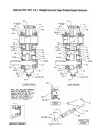
For Taper Bushed: Mount reducer on driven shaft per
instruction sheet No. 499629 packed with tapered
bushings.
4. Install sheave on input shaft as close to reducer as
practical. (See Fig. 2)
5. Install motor and V-belt drive so belt will
approximately be at right angles to the center line between
driven and input shaft. (See Fig. 3) This will permit
tightening the V-belt with the torque arm.
6. Install torque arm and adapter plates using the long
reducer bolts. The bolts may be shifted to any of the holes
on the input end of the reducer.
7. Install torque arm fulcrum on a flat and rigid support
so that the torque arm will be approximately at right angles
to the center line through the driven shaft and the torque
arm anchor screw. (See Fig. 4) Make sure that there is
sufficient take-up in the turnbuckle for belt tension
adjustment when using V-belt drive.
CAUTION: Unit is shipped without oil. Add proper amount
of recommended lubricant before operating. Failure to
observe this precaution could result in damage to or
destruction of the equipment.
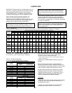
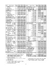
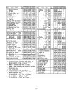
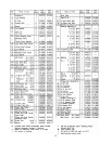
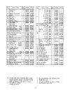
8. Fill gear reducer with recommended lubricant. See
page 3, table 1.