3
LUBRICATION
IMPORTANT: Because reducer is shipped without oil, it is
necessary to add the proper amount of oil before running.
Use a high-grade petroleum base rust and oxidation
inhibited (R&O) gear oil - see tables. Follow instructions
on reducer warning tags, and in the installation manual.
Under average industrial operating conditions, the
lubricant should be changed every 2500 hours of
operating or every 6 months, whichever occurs first. Drain
reducer and flush with kerosene, clean magnetic drain
plug and refill to proper level with new lubricant.
CAUTION: Extreme pressure (EP) lubricants are not
recommended for average operating conditions. Failure to
observe these precautions could result in bodily injury.
CAUTION: Too much oil will cause overheating and too
little will result in gear failure. Check oil level regularly.
Failure to observe this precaution could result in bodily
injury.
Under extreme operating conditions, such as rapid rise
and fall of temperature, dust, dirt, chemical particles,
chemical fumes, or oil sump temperatures above 200°F,
the oil should be changed every 1 to 3 months, depending
on severity of conditions.
CAUTION: Do not use EP oils containing slippery
additives such as graphite or molybdenum disulfide in the
reducer when backstop is used. These additives will
destroy sprag action.
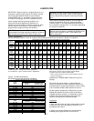
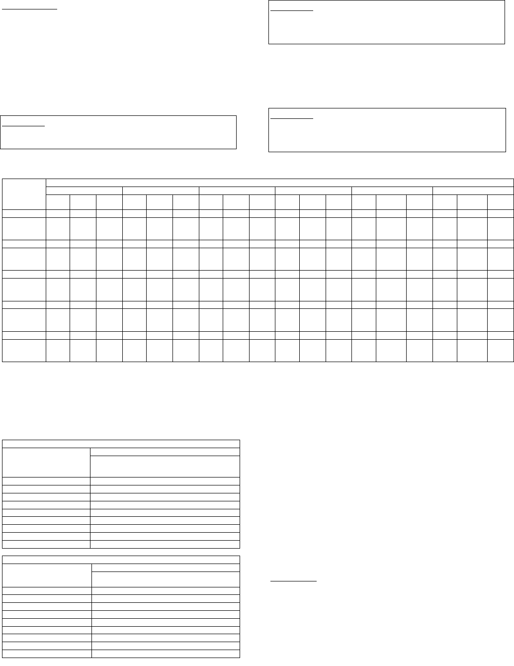
Table 1 - Oil Volumes
•
Consult DODGE for proper oil level for reducers with backstops and which are mounted in C-position or D-position.
Approximate Volume of Oil Required to Fill Reducer to Oil Level Plug
† Position A † Position B † Position C † Position D † Position E † Position F
Reducer
Size
TXT/HXT
Oz.
c
Qt.
L Oz.
c
Qt.
L Oz.
c
Qt.
L Oz.
c
Qt.
L Oz.
c
Qt.
L Oz.
c
Qt.
L
305A 28 .88 .83 48 1.50 1.42 44 1.38 1.30 44 1.38 1.30 80 2.50 2.37 100 3.13 2.96
309A
315A
325A
48 1.50 1.42 48 1.50 1.42 24 .75 .71 72 2.25 2.13 84 2.63 2.48 96 3 2.84
405A 48 1.50 1.42 72 2.25 2.13 68 2.13 2.01 60 1.88 1.77 128 4 3.79 166 4.88 4.62
409A
415A
425A
60 1.88 1.77 72 2.25 2.13 40 1.25 1.18 56 1.75 1.66 108 3.38 3.19 136 4.25 4.02
505A 108 3.38 3.19 136 4.25 4.02 124 3.88 3.67 120 3.75 3.54 248 7.75 7.33 288 9 8.52
509B
515B
525B
104 3.25 3.08 128 4 3.79 104 3.25 3.08 128 4 3.79 224 7 6.62 272 8.50 8.04
605 144 4.50 4.3 184 5.75 5.4 144 4.50 4.3 160 5 4.7 384 12 11.4 352 11 10.4
609
615
625
136 4.25 4.0 160 5 4.7 136 4.25 4.0 160 5 4.7 276 8.63 8.2 292 9.13 8.6
705 240 7.50 7.1 288 9 8.5 240 7.50 7.1 296 9.25 8.8 608 19 18 552 17.25 16.3
709
715
725
208 6.50 6.1 256 8 7.6 232 7.25 6.9 296 9.25 8.7 492 15.38 14.6 524 16.38 15.5
† Refer to Figure 1 on page 2 for mounting positions.
c U.S. Measure: 1 quart = 32 fluid ounces = .94646 liters.
Note: If reducer position is to vary from those shown in figure 1,
either more or less oil may be required. Consult Dodge.
If output is less than 15 RPM, consult Dodge.
• Below 15 RPM output speed, oil level must be adjusted to reach the
highest oil level plug (P.).
Table 2 – Oil Recommendations
ISO Grades for Average Operating Conditions
Ambient Temperatures of 15ºF thru 60ºF
Reducer Size
Output
RPM
TXT3A–7
HXT3A–7
TXT305A–705
HXT305A–505A
301–400 220
201–300 220
151–200 220
126–150 220
101–125 220
81–100 220
41–80 220
11–40 220
1–10 220
Ambient Temperatures of 50ºF thru 125ºF
Reducer Size
Output
RPM
TXT3A–7
HXT3A–7
TXT305A–705
HXT305A–505A
301–400 320
201–300 320
151–200 320
126–150 320
101–125 320
81–100 320
41–80 320
11–40 320
1–10 320
Guidelines for TORQUE-ARM™ Reducer Long-Term
Storage
During periods of long storage, or when waiting for
delivery or installation of other equipment, special care
should be taken to protect a gear reducer to have it ready
to be in the best condition when placed into service.
By taking special precautions, problems such as seal
leakage and reducer failure due to lack of lubrication,
improper lubrication quantity, or contamination can be
avoided. The following precautions will protect gear
reducers during periods of extended storage:
Preparation
1. Drain the oil from the unit. Add a vapor phase corrosion
inhibiting oil (VCI-105 oil by Daubert Chemical Co.) in
accordance with Table 3.
2. Seal the unit airtight. Replace the vent plug with a
standard pipe plug and wire the vent to the unit.


