


Note – 3.0 V is the minimum allowable voltage for battery backup. When the power
output drops below 3.0 V, the real-time clock may not operate over the specified full
temperature range and this can significantly extend the time to first fix.
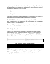
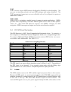
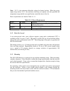
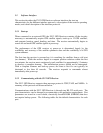
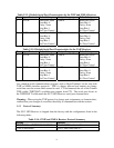
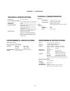
Power requirements are listed in Table 3.1.1-1
Table 3.1.1-1 Power Requirements
Signal Voltage Current
Battery Backup +3.0 to 12 0 µA with prime power; 20 µA @ 3.3 V, 25
o
C
without prime power
Ground 0 -
VCC +9 to 32 25mA typ @ 12V
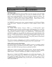
3.1.2 Pulse Per Second
A ten microsecond wide, open collector negative going pulse synchronized UTC is
available on Pin 9 or ports 1 and 2. This pulse is issued once per second with the falling
edge of the pulse synchronized with UTC. The falling edge of the pulse is typically less
than 20 nanoseconds.
The timing accuracy is +/- 50 nanoseconds and is available only when the valid position
fixes are being reported. Repeatability checks of 10 sets of 100 second samples taken
over a period of 20 minutes showed an average variation of approximately 100
nanoseconds (not allowing for SA).
3.1.3 Mounting
The SV12 GPS Receiver is packaged in an anodized aluminum casing. When mounting,
consider vibrations. If the vibration is within the design specifications, then the receiver
can be hard-mounted. If not, select a mount that dampens the vibration enough to bring
the receiver back into specification.
For mounting, utilize metal screws through the four provided screw holes incorporated
into the enclosure. Select a screw length which extends a safe distance beyond the
mounting surface and secure these screws with nuts and lock washers. CTI recommends
that you use four number 8 pin-head machine screws.
6