


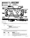

page 3 MAN#650231:A
6. Fuel sender installation (optional tube sender from Dakota Digital):
a. To mount the sensor you will need to drill a hole in the fuel tank. Use a 1” hole saw, and drill a hole adjacent to
the small dimple on the gas tank closest to the passenger side of the vehicle. Use a fuel safe sealant and coat
the supplied cork gasket to provide a leak free seal from the tank to the sensor. Secure the sensor with the
supplied stainless screws. DO NOT OVER TIGHTEN THE SCREWS.
b. Attach the wiring harness provided with the sender. Connect the Red wire to the POS terminal. Connect the
Black wire to the NEG terminal. Connect the GREEN wire to the SEND terminal.
c. Route the wire harness up to the gauge mounting location using supplied zip ties to tie the harness so that it will
not be pinched or damaged.
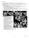
7. Locate the stator rotation detection wire (red wire,
pin 6 in the 8 pin connector coming out of CDI
module located near the battery) and place the
included T-tap connector onto it using a pair of
pliers. This wire will be used for the tachometer
signal.
8. Route the wires from the UTV gauge through the hole in the gauge opening and place gauge into opening. Secure
the gauge with the three provided washers and thumb nuts.
9. Route the yellow tach wire to the T-tap connector for the tachometer and plug into the connector.
10. Plug the four pin connector from the oil pressure harness into the four pin connector in back of gauge.
11. If using a separate fuel sender plug the three pin connector from the fuel sender harness into the three pin connector
in the back of the gauge.
12. Locate the three gauge connectors in the Rhino harness. These connectors will be located close to the gauge mount
location on the under hood side of the dash panel.
13. Plug the 6 pin gauge connector into the 6 pin connector on the Rhino.
14. Plug the 4 pin gauge connector into the 4 pin connector on the Rhino
15. Plug the 3 pin gauge connector into the 3 pin connector on the Rhino.
16. Reconnect battery.
17. Turn the key on and verify that the gauge functions as expected.
18. Start engine and check for oil and water leaks. Shut off engine.
19. If there are no oil or water leaks, reinstall the floor panels, engine covers and seats as described in the service
manual.
20. Installation is now complete. If you experience difficulties check the troubleshooting section in this manual.
SETUP
To enter the setup menu, press and hold the left switch while turning the key on. If your speed calibration differs from
stock due to non-stock tires or gears and you will be calibrating the speedometer, press and hold the left switch while
starting the engine.
-Press the left switch to move through the menus or change the settings after a menu option is selected.
-Hold the left switch for more than 2 seconds to scroll through options or settings
-Press the right switch to select a menu option or to save a setting and go back to the menu.
SETUP Release switch to enter setup menu
INFO Information menu
VER Displays software version
U113 Current software version
SP CAL Displays current speed cal value
160000 Current speed cal value
MAIN Returns to info menu
SPEED Speed gauge menu
UNIT Select unit for speed
Toggle between MPH and KPH (select unit to use for calibration)
AUTO Auto calibrate speed to a marked mile or kilometer