


Manual # 650340
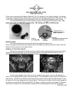
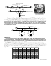
Back View of Gauge
Dim Input (active high +12V)
BLUE wire
Switch Input (active high +12V)
GREEN wire
Optional momentary
push button switch
Connect to main
chassis ground
+12V
KEY ON POWER
Sender
(to stock fuel level sensor)
+12V
KEY ON POWER
+12V
KEY ON POWER
Optional toggle
switch
If you are installing multiple MCL-3K gauges you can tie the GREEN wires together and then to
one switch. The same is true for the BLUE wire, wire all of them to one switch.
If you have a MCL-3K Tachometer, it will actually serve as the dimming “switch”. The BLUE wire
on any of the MCL-3K Tachs will provide a +12V output for the dimming function. The gauge has a light
sensor behind the lens and when the ambient light is dim or low it will “turn on” the output and supply
+12V to the BLUE wire. You will not need to wire in a toggle switch if you have an MCL-3K tachometer
and choose to wire it this way.
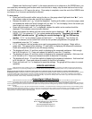
Back View of Gauges
Dim Input (active high +12V)
BLUE wire
Switch Input (active high +12V)
GREEN wire
Optional momentary
push button switch
+12V
KEY ON POWER
+12V
KEY ON POWER
Optional toggle
switch
Continue wiring to other
MCL-3K gauges
GAUGE SETUP
The fuel gauge can be set to read two stock Harley sensor curves, see setup procedure below for
correct sender selection. There is also a non-adjustable warning feature that will flash the gauge at any
reading below 10% as a low fuel warning indicator. You may also choose to select a custom fuel curve,
where the gauge will “learn” your sensor as you add fuel.
The GREEN switch input wire, in the two pin connector, is used to enter setup. If you are only
installing one or a couple Dakota Digital MCL-3K gauges set up may seem a little strange since they are
designed to work as a set, however you’ll simply cycle through a few screens to get to the desired gauge.
The table below shows what will be on the gauge with each button press, or tapping the GREEN wire
high +12V.
Speed Tach Oil psi Oil temp Fuel Volt
1
st
- 1 -
- 1 - - 1 -
- 1 -
CL
CLCL
CL
-
- -
- 1 -
1 - 1 -
1 -
- 1 -
- 1 - - 1 -
- 1 -
- 1 -
- 1 - - 1 -
- 1 -
- 1 -
- 1 - - 1 -
- 1 -
2
nd
SPd
SPdSPd
SPd
- 2 -
- 2 - - 2 -
- 2 -
- 2 -
- 2 - - 2 -
- 2 -
- 2 -
- 2 - - 2 -
- 2 -
- 2 -
- 2 - - 2 -
- 2 -
- 2 -
- 2 - - 2 -
- 2 -
3
rd
- 3 -
- 3 - - 3 -
- 3 -
tCH
tCHtCH
tCH
- 3 -
- 3 - - 3 -
- 3 -
- 3 -
- 3 - - 3 -
- 3 -
- 3 -
- 3 - - 3 -
- 3 -
- 3 -
- 3 - - 3 -
- 3 -
4
th
- 4 -
- 4 - - 4 -
- 4 -
- 4 -
- 4 - - 4 -
- 4 -
PSI
PSIPSI
PSI
- 4 -
- 4 - - 4 -
- 4 -
- 4 -
- 4 - - 4 -
- 4 -
- 4 -
- 4 - - 4 -
- 4 -
5
th
- 5 -
- 5 - - 5 -
- 5 -
- 5 -
- 5 - - 5 -
- 5 -
- 5 -
- 5 - - 5 -
- 5 -
F or C
F or CF or C
F or C
- 5 -
- 5 - - 5 -
- 5 -
- 5 -
- 5 - - 5 -
- 5 -
6
th
- 6 -
- 6 - - 6 -
- 6 -
- 6 -
- 6 - - 6 -
- 6 -
- 6 -
- 6 - - 6 -
- 6 -
- 6 -
- 6 - - 6 -
- 6 -
FUL
FULFUL
FUL
- 6 -
- 6 - - 6 -
- 6 -
7
th
- 7 -
- 7 - - 7 -
- 7 -
- 7 -
- 7 - - 7 -
- 7 -
- 7 -
- 7 - - 7 -
- 7 -
- 7 -
- 7 - - 7 -
- 7 -
- 7 -
- 7 - - 7 -
- 7 -
uLt
uLtuLt
uLt
8
th
- 8 -
- 8 - - 8 -
- 8 -
- 8 -
- 8 - - 8 -
- 8 -
- 8 -
- 8 - - 8 -
- 8 -
- 8 -
- 8 - - 8 -
- 8 -
- 8 -
- 8 - - 8 -
- 8 -
- 8 -
- 8 - - 8 -
- 8 -
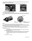
Connection shown with
optional spade terminals