


MAN# 650304:F
Wiring
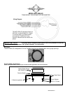
The gauge is a direct plug in on 2004 and newer bikes. The only wiring, which is optional, is for the indicator lights
and auxiliary pressure/temp gauges if you choose.
POWER
Constant battery power and key switched power are supplied by the stock harness.
GROUND
Ground is supplied by the stock harness.
STATUS AND WARNING INDICATORS
An extra 6 pin harness is supplied for the indicators not found in the stock
speedometer harness connector.
The high beam indicator is activated by 12 volts at the purple wire. The turn
signals can be activated by the data bus on most models.
The neutral and low oil indicators are activated by ground at their
respective hook-up wires. These can be connected to the same wires that the
stock indicator lights would be connected to. The low oil wire is brown and the
neutral wire is white/green.
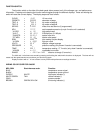
Several indicators are supplied on the stock wiring harness. Some of
these may not be active on your motorcycle. These include the security (red key
symbol), engine (red ‘E’), ABS (red ‘ABS’), low fuel (amber fuel pump symbol),
and cruise control (arrow and circle symbol). All of these indicators have a fixed
color except for the cruise control. This will be red or blue when the cruise switch is on and change to green when the
cruise is engaged.
LOW VOLTAGE WARNING
When the voltage drops below the warning limit with the engine running, “LO” and your current voltage will be
displayed. (default warning limit is 11.0V)
SPEEDOMETER
The speedometer is read from the engine control module (ECM) data bus. This can be calibrated to allow for
differences in tires or gearing. Calibration is discussed in a later section.
TACHOMETER
The tachometer is read from the ECM data bus.
The bar displays rpm x1000 with a range of 350 – 7000 rpm. The rpm can also optionally be shown on the
message display.
CLOCK
The clock uses a 12 hour format and can be set by pressing and holding the switch while the clock is displayed.
After the switch is held for a few seconds the hours will begin flashing. Momentarily pressing the switch will change the
hours, holding the switch will move to the minute set and the minutes will begin flashing. Momentarily pressing the switch
will now change the minutes. Holding the switch will exit the clock set mode.
GAUGE SETUP AND CALIBRATION
The setup menus are entered by holding the switch in while turning the key on. The menus are as follows:
Menu Description
dIag (EngInE, seCURE, ABS, DONE) read diagnostic codes
ADJvST (FASTER, SLOWER) (75 - 125) adjust calibrate speed
vnIt (MPH, km/h ) select speed unit
S SET (OFF, 500 - 7500) miles to service setting
PERF (ON, OFF) turn on/off performance displays
NIGHT (ON, OFF) turn on/off automatic night dimming
UPDATE (1, 2, 3) set digital rpm update rate
WXARN
RPM
(shown on bar graph) set rpm shift warning point
COLOR
RPM
(shown on bar graph) select rpm bar graph color, red or green
WXARN
V
(9.0- 12.1) set low volt warning point
Sender
P
(75, 150, 400) select pressure sender type
WXARN
P
(LO 5 - 36) (HI 37 - 75, 75 - 150, or 150 - 300) set pressure warning points
SET FC (HEAD F, HEAD C, 400F, 200C, 302F, 151C) select temperature sensor and unit
HI F-C (200F - 350F or 93C - 176C) set temperature warning point
GEAR (DONE, PRESET, LEARN) transmission gear display selection
FUEL (DONE, TEST, RESET, ADJUST) low fuel light setup
CL CAL (-8 - 7) adjust clock calibration
INFO display gauge revision code on speedometer
range (DONE, sender, RESET) miles to empty setup
odoMK- one-time odometer preset
E
A
B
MPH
km/h
N
RPM
ABS
0
1
2
3
4
5
6
7
V
P