


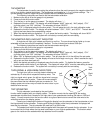
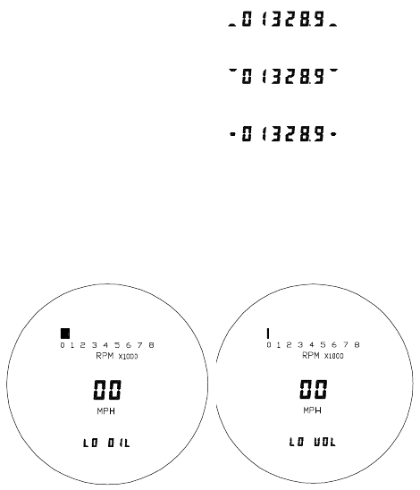
NEUTRAL INDICATOR
The neutral indicator is activated when the blue wire is grounded. Connect
this wire to the neutral switch or to the negative side of the neutral indicator light.
When the indicator is activated, a bar on either side of the odometer display will move
up and down as shown in the diagram.
NIGHT DIMMING
Your display system has a dimming feature that dims the display intensity. Normally the system is at full
brightness for daytime viewing. When the brown wire has 12 volts the display intensity will be reduced. A
toggle or on/off push button switch can be connected to this wire if this feature is desired. To have the system
at full brightness all of the time leave the brown wire disconnected.
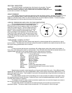
LOW OIL PRESSURE AND LOW VOLTAGE INDICATORS
The low oil pressure warning is activated when the
gray wire is grounded and there is a tachometer signal.
Connect this wire to the oil pressure switch or the negative
side of the oil warning light. The low voltage warning is
activated when the voltage at the red power wire drops
below 11 volts and there is a tachometer signal. The
warning message will be displayed in the odometer area.
Press the function switch will clear the warning and return
the mileage reading for 30 seconds. If there is both a low
voltage and low oil warning at the same time, the low oil will
be displayed.
TURN SIGNAL CANCEL OUTPUT
The display system also has a speed output signal for cycles equipped with an automatic turn signal
cancel module. The white wire from the main harness should be connected to the module where the wire from
the original analog speedometer was connected.
WIRING
In order to ensure that there are no problems with voltage drops causing the system to shut down, a
heavy duty, solid state ignition switch is recommended. Also, the black wire should be connected directly to the
negative battery terminal to avoid erratic operation due to a poor ground connection.
The wire color code for the main display system harness is as follows:
RED +12 volt with key on
BLACK ground (connect directly to battery)
YELLOW tachometer signal
PURPLE high beam indicator
ORANGE left turn indicator
GREEN right turn indicator
BLUE neutral indicator
GRAY oil warning
WHITE/BLUE function (trip select/reset) switch
WHITE turn signal cancel signal (to auto cancel module)
BROWN night dimming
Speedometer connection varies depending on the year and model of the cycle. Using different speed
adapter kits the speedometer can read a speedometer cable, a stock electric transmission speed sensor, or an
aftermarket gear-tooth sensor. Each adapter kit connects to the speedometer using the three pin connector on
the bottom of the system.
The cable adapter accepts a 5/8” thread fitting and can be mounted to the bottom of the system using
the supplied bracket or remote mounted. Cycles that have a metric-threaded speedometer cable will need to
have the cable modified or replaced.
The adapter harness for using a stock transmission speed sensor converts the triangular connector to
the in-line connector on the speed/tach system.
The gear-tooth sensor kit consists of a two-terminal sensor and a harness to connect it to the
speed/tach system. The sensor needs to be mounted within 1/8” of the teeth on a final drive gear.