


TACHOMETER
The tachometer is used by connecting the yellow wire from the main harness to the negative side of the
coil or to an ignition module tach output. The tachometer is adjustable for 1, 2, or 8 cylinder settings. The 1
cylinder setting is used for single-fire ignition systems without a buffered tach output.
The following instructions are used to set the tachometer calibration:
1. Make sure the key is off so the gauge is not powered.
2. Press and hold the function switch.
3. Turn the key on so the gauge is powered. The display will show “ -- “.
4. Release the function switch. The display will switch between “AUtO” (auto cal), “AdJ” (adjust), “CYL”
(cylinder select), and “SEt” (shift bar). The odometer will show “SELECt”
5. When “CYL” is displayed press the function switch. This will place the unit in the tach calibration mode.
6. Release the function switch. The display will switch between “1CYL”, “2CYL”, and “8CYL”. The tach bar will
light up two bars above the corresponding number.
7. When the desired setting is displayed, 1, 2, or 8, press the function switch. The display will show “tACH”.
8. Release the function switch. The system will now start up normally with the new setting.
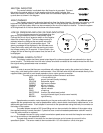
TACHOMETER RED LINE/SHIFT INDICATOR
A single bar will light up to indicate a shift point or red line. The rpm where the bar lights up is user
selectable and can be turned off completely if desired. The bar is factory set to about 5000 rpm.
The following instructions are used to set the tachometer warning bar:
1. Make sure the key if off so the gauge is not powered.
2. Press and hold the function switch.
3. Turn the key on so the gauge is powered. The display will show “ -- “.
4. Release the function switch. The display will switch between “AUtO” (auto cal), “AdJ” (adjust), “CYL”
(cylinder select), and “SEt” (shift bar). The odometer will show “SELECt”
5. When “SEt” is displayed press the function switch. This will place the unit in the shift/red line set mode.
6. Release the function switch. The bar display will start at 2 and begin moving up. After it reaches the top it
will go out and then start back at 2.
7. When the desired rpm setting is displayed press the function switch. To disable this feature, press the
function switch while the bar is not displayed. The display will show “tACH” once the new setting is stored.
8. Release the function switch. The system will now start up normally with the new setting.
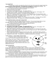
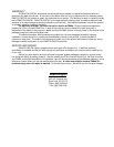
TURN SIGNAL & HIGH BEAM INDICATORS
The right turn, left turn, and high beam indicators are
activated by 12 volts at their respective hook-up wires. The
right turn signal wire is green, the left turn signal wire is orange,
and the high beam wire is purple. These can be connected to
the same wires that the indicator lights are connected to. The
display system wire colors may not match the wire colors in your
electrical wire harness.
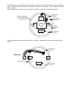
TRIP ODOMETER
The trip odometer is activated by the push button
function switch supplied with your display system. The button mounts into the opening for the analog
speedometer trip reset that is located on the right side of your speedometer housing (left side on 1995 and
newer). Connect one wire from the function switch to a ground terminal and connect the other wire to the
white/blue wire from the display system.
Pressing and releasing the button will toggle the display from the odometer to the trip odometer or from
the trip odometer to the odometer. Pressing and holding the button while the trip odometer is displayed will
reset the trip odometer. The trip odometer will read from 0 to 999.9 miles.
The sealed push button function switch supplied with the system will operate the trip odometer. It can
be mounted into the hole where the trip reset handle was on your original speedometer. The function switch
goes on the inside and the sealed switch cap attaches from the outside.
Left
Turn
Tach
warn
Right
Turn
High
Beam