


PW 3500 Series
Technical Information
Operator Controls
The PW 3500 Series has a
refined control handle, which
improves operator comfort and
productivity.
The Crown PW 3500 Series has
dual, soft urethane twist grips
with automatic return to neutral
when released. Two textures and
a unique “cam” design aid in
plugging, steering and long dis-
tance travel. On the control pod
are full width raise, lower and
horn buttons for easy actuation.
Third speed selector in control
handle may be used to shut off
high speed when operating in
congested areas. Reversing
button in control handle reverses
direction of travel, if button should
come in contact with operator.
Electrical System
24-volt electrical system
(PW 3520-60/80)
12-volt electrical system
(PE 3510-60)
Series-wound, high-torque, fan-
cooled, Crown manufactured
drive motor for reliability and
ease of service.
Series-wound, high-torque,
lift motor
Traction control systems:
Resistor control has four heavy-
duty contactors with silver tips.
Solid-state time relay on resistor
control between 2nd and 3rd
speeds
provide controlled
acceleration. Resistor is
standard on the PW 3500
Series. Transistor control is
optional on 24-volt models.
Transistor control has many
benefits; maximum energy effi-
ciency, reduced maintenance
and infinite speed control.
Crown transistor controls feature
a 250 amp rated system; a
bypass contactor for maximum
current in heavy loading, ramping
applications; arc-less contactor
operation; ramp start; and a
sealed enclosure that protects
the transistor control from water,
contaminants, etc.
Lift limit switch operates at
maximum lift height to shut off
pump motor.
Control and power circuits
are fused.
To facilitate pallet entry/exit
Crown has engineered several
features into their fork assembly.
Standard-tip forks have pallet
entry rollers to lift fork over
bottom board of pallet. Rollers
are made of high molecular
weight polyethylene with .75"
axle and roll pin.
Abrasion-resistant steel entry/exit
slides on both sides of each fork
have convex bottom surfaces to
prevent snagging as forks move
over bottom boards of pallet.
One piece design with radiused
edges are welded away from
contact point of slide.
New exit roller design prevents
load wheel from dropping after
crossing bottom board. The 4"
wide, steel exit roller is posi-
tioned directly behind the load
wheel to
keep the fork rolling.
New entry/exit
slide design also
assists in trouble free pallet
entry/exit.
Fork adjustment is done at the
toe with no need to remove a
cover plate. Fork heel height
adjustment is done quickly with-
out removing battery. Quick and
easy fork adjustment promotes
servicing of fork assembly to
keep pallet entry/exit productive.
Pull rod design incorporates a
replaceable “tenon” design for
fast servicing of pull rod while
still in the truck.
Power Unit Structure
Rugged steel doors are sus-
pended on heavy-duty pin
hinges. Doors swing wide for
good access. Doors also can be
lifted off for unrestricted service
access. Door bolts have exclu-
sive convex design that mates
with concave door holes for fast
reinstallation of bolts. Heavy-steel
skirt surrounds entire area.
Brake
Internal expanding mechanical
brake with 4.5" drum and
bonded brake linings. Brake
drum is mounted on drive
motor shaft and braking effort
is transmitted through the gear
reductions. Brake is actuated by
control handle position.
Power disconnect
All wiring color coded
Key switch
175 amp SB connector
(PW 3520-60/80) 350 amp
connector (PW 3510-60)
Horn
Hydraulic System
Heavy-duty pump, motor,
reservoir and control are assem-
bled into one unit. A centrally
located lift cylinder,
mounted
vertically, is equipped
with long-
life polyurethane packing.
Pressure-compensating flow
control valve is intergal part
of valve block and regulates
maximum lowering speed.
Overload valve protects
hydraulic components.
Drive Unit
All gear drive from drive motor to
drive wheel axle. Drive tire axle
is mounted in the drive unit on
both sides for maximum strength
in rough floor or docking appli-
cations. Drive unit is top and
bottom mounted. Top mount is
a large, tapered roller bearing for
vertical or horizontal forces.
Bottom mount has four shock
mounted rollers on drive unit
running in a hardened steel roller
race. Gear train runs in oil-filled,
sealed housing.
Caster System
Crown has designed two
optional caster systems for the
PW 3500 Series to meet high-
volume warehouse requirements.
Option 1: Quick adjustment
casters enable braking, traction,
steer effort and stability to be
“balanced” based on your
specific applications.
Option 2: All of the advantages
of quick adjustment casters are
yours, in addition to a torsion
bar suspension that maximizes
stability on tall, unwieldy and less
stable loads.
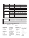
Fork Assembly
Fork width - 9.12" on standard-
tip fork models, fork spread - 22"
and 27" standard on standard-
tip models. 23" - 26" spread
available in one-inch increments.
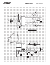
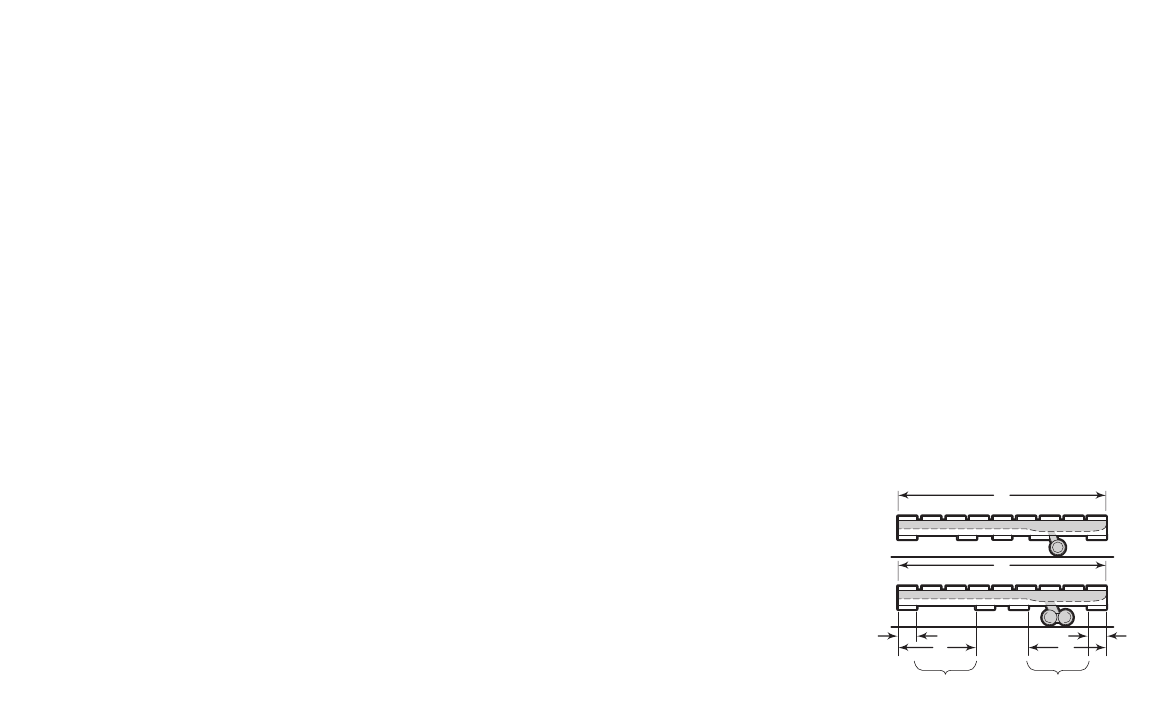
Pallet Planning Guide
On PW models, the load wheel
will drop in the second opening
of the pallet. When “A” dimen-
sion equals nominal fork length,
“C” dimension is 6" maximum
and “B” is 14" minimum. On
models with tandem load
wheels, the “C” dimension
should be 6" maximum and the
“B” dimension should be 17"
minimum. Customers that need
tandem load wheel trucks, but
use pallets with smaller open-
ings, may be accommodated if
the maximum lift height of the
truck is reduced. Contact your
local Crown dealer for details.
Other Options
1. Audible travel alarm
2. Flashing lights
Safety considerations and
dangers associated with
audible travel alarms and
flashing lights include:
• Multiple alarms and/or lights
can cause confusion.
• Workers ignore the alarms
and/or lights after day-in and
day-out exposure.
• Operator may transfer the
responsibility for “looking out”
to the pedestrians.
• Annoys operators and
pedestrians.
Dimensions and performance
data given may vary due to
manufacturing tolerances.
Performance is based on an
average size vehicle and is
affected by weight, condition of
truck, how it is equipped and the
conditions of the operating area.
Crown products and specifica-
tions are subject to change
without notice.
C
Crown Equipment Corporation
New Bremen, Ohio 45869 USA
Tel 419-629-2311
Fax 419-629-3796
crown.com
Because Crown is continually improving its products,
specifications are subject to change without notice.
Crown and the Momentum symbol are trademarks of
Crown Equipment Corporation.
Copyright 1993-2005 Crown Equipment Corporation
SF12156 Rev. 4/05
Printed in U.S.A.
A
A
BB
CC
First
Opening
Second
Opening