


INSTALLATION CAUTIONS & WARNINGS
BEFORE BEGINNING, check all vehicle manufacturer cautions and warnings regarding electrical service (AIR
BAGS, ABS BRAKES, AND BATTERY).
DO NOT ROUTE ANY WIRING THAT MAY BECOME ENTANGLED with brake, and gas pedals, steering
column, or any other moving parts in the vehicle.
REMOVE MAIN SYSTEM FUSE(S) before jump starting the vehicle or charging the battery at high boost.
DAMAGE MAY OCCUR TO SYSTEM IF PROPER PRECAUTIONS ARE NOT OBSERVED.
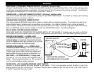
COMPONENT MOUNTING
CONTROL MODULE: Locate the module underdash as high as possible. Driver’s Side usually provides an
easy location for the majority of the wiring connections. Keep the module away from moving parts such as
brake/gas/clutch pedals, or the steering column. The Placement of the module will affect the distance from
which the remote transmitter can control the unit. The antenna wire should be routed away from any metal if
possible. DO NOT alter the length of the antenna wire, route it with other wires, or ground the antenna wire.
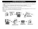
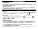
OVERRIDE / PROGRAM BUTTON: Mount the button in a hidden but accessible location. It is used for
emergency-disarm (when optional starter disable is installed) without the use of the transmitter and for
programming certain features.
LED: The red LED provides a useful theft deterrent and serves as the indicator when changing
programming options. Choose a visible location in the dash where running the wire down through the dash
will not create any problems. Always check behind surfaces before drilling any holes!
WIRING
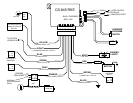
YELLOW WIRE: IGNITION SWITCHED “ON” AND “START” +12 VOLTS
Connect to an ignition wire (or fuse in the fuse box) that shows +12 Volts when the key in both “On” and “Start”
positions.
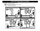
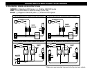
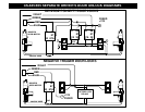
VIOLET WIRE: (-) PASSENGER(S) DOOR UNLOCK OUTPUT (Optional, requires relay)
Connects to unlock circuit for passenger door(s) when using separate driver’s door unlock option. See DOOR LOCK
WIRING for configuration options.
BLUE WIRE: (-) HORN HONK/CHIRP OUTPUT (Optional, requires relay)
Connects to terminal 85 of a relay. Connect terminal 86 to +12V Constant. Connect terminal 87 to +12V or GROUND
depending on the type of horn activation circuit in the vehicle. Connect terminal 30 to the horn activation circuit.