


1
CSI MODEL 10164-L SAMPLER CONTROL CABLE
FOR USE WITH ISCO AND SIGMA AUTOSAMPLERS
The 10164-L sampler control cable enables a datalogger to trigger an Isco, American Sigma, or
connector-compatible autosampler. Through this cable, the datalogger can inhibit the sampler from
running its programmed sampling routine and sense and record when the sampler indicates that it has
taken a sample. The following examples illustrate its use. Each of these functions are independent of
the others and you may combine functions as desired. You should insulate and tuck out of the way any
unused wires.
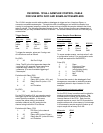
Trigger Sampler
Wire color CR10 21X BDR320
purple G Ground GND
yellow C2 Control 2 C2
red 12V +12 12V
clear G Ground GND
To trigger the sampler, pulse port 2 using a set
of instructions such as follows:
Do (P86)
1: 42 Set Port 2 High
; Note: The 50 in the third parameter keeps the
; port high for 0.5 seconds. Some users have
; reported using a delay of 1 sec (100 in
; parameter 3) to ensure reliable triggering of
; the sampler.
Excitation with Delay (P22)
1: 1 Ex Channel
2: 0 Delay W/Ex (units = 0.01 sec)
3: 50 Delay After Ex (units = 0.01
sec)
4: 0 mV Excitation
Do (P86)
1: 52 Set Port 2 Low
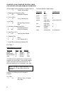
For the CR10 and the 21X, you can also supply
the trigger signal from switched excitation if no
control ports are available. In this case,
connect the yellow cable to the desired
excitation channel (say E3) and pulse the
channel using Instruction 22 as follows:
Excitation with Delay (P22)
1: 3 EX Chan (or the channel
you select)
2: 50 Delay w/EX (units=0.01sec)
3: 0 Delay after EX (units=0.01sec)
4: 2500 mV Excitation
Sense Sampler Event Markers
Pulse port method:
Wire color CR10 21X BDR320
purple G Ground GND
orange P1 Pulse 1 P1
clear G Ground GND
To sense sampler events, use Instruction 3 with
a configuration code of 0 (no configuration code
or Reps are required for the BDR320):
Pulse (P3)
1: 1 Reps
2: 1 Pulse Input Chan
3: 0 High frequency
(configuration code)
4: 2 Loc [:EVENTS]
5: 1 Mult
6: 0 Offset
To record the events in the datalogger's final
storage area, remember to totalize the events
temporarily stored in Input Location 2 in this
example.
CR10 control port interrupt method:
For the CR10, there is another useful method for
sensing and recording sampler events. This
method uses the control port 8/subroutine 98
interrupt feature of the CR10. Each time the
sampler reports an event, the CR10 records the
sample number with a time stamp in final storage.
In this example, sampler events will show up as
output arrays with an array ID of 400.
Wire color CR10
purple G
orange C8
clear G