


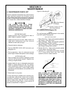
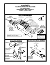

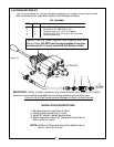


5-10 MOUNTING BRACKET EYEBOLT
Install eyebolt to each mounting kit center bracket
and secure with hardware. Figure 5-2.
Figure 5-2
5/8” Locknut
Mounting Kit
Center Bracket
CAUTION
LIFT AND SUPPORT ALL LOADER COM-
PONENTS SAFELY.
32
Eyebolt
5/8 x 3-1/2” Gr. 5
Hex Bolt
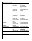
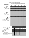
Verify that all mounting kit hardware has been
torqued as specified before installing loader.
A. Identify hardware size and grade.
B. Refer to Torque Specifications, page 34, and find
correct torque for your hardware size and grade.
C. Torque hardware to this specification unless oth-
erwise specified.
IMPORTANT
To prevent mounting kit hardware from loosen-
ing during loader operation always torque
mounting kit hardware to specified torque.
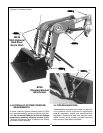
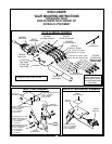
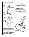
5-11 STANDARD BUCKET &
LEVEL INDICATOR ROD
A. Attach boom and hydraulic cylinders to bucket
using fasteners provided, as shown in Figure 5-3.
B. Place indicator rod through guide tube and posi-
tion as shown. (Level Indicator Rod and guide tube
may be mounted on the inside or outside of boom,
as desired.) Attach guide tube to mainframe using
1/4” bolt, flat washer and lock nut. Do not over-tighten
1/4” locknut as this will prevent guide tube from piv-
oting freely.
C. Attach lower end of indicator rod to bucket brack-
et using cotter pins and flat washers.
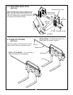
Support the loader by using a hoist. Refer to
Mounting The Loader, page 10, to install the loader
to mounting brackets previously installed on tractor.
M246
Figure 5-3
Standard Bucket
Level Indicator Rod
Guide
Tube
Boom
Hydraulic Cylinder
Bucket Pins &
Fasteners
M146
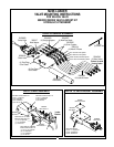
1/2” Lockwasher
1/2” Hex Nut
Eyebolt
1/2 x 3” Gr. 5
Hex Bolt
Mounting Kit
Center Bracket