


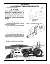
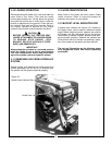
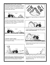

3-6 LOADER MOUNTED SERIES CON-
TROL VALVE EQUIPPED WITH SINGLE
LEVER CONTROL HANDLE
If your loader utilizes a loader mounted series con-
trol valve equipped with single lever control handle,
it will function as shown in Figure 3-2.
3-4 EXTERNAL LOADER AND/OR TRAC-
TOR VALVE.
NOTE
When properly installed, the tractor remote valve
or external valve control lever/levers will control
the loader hydraulic circuits as described below.
Refer to tractor Operator’s Manual for further
explanation of tractor remote control
lever/levers.
IMPORTANT
Contaminants in hydraulic fluid can cause valve
spools to stick. BE ALERT when operating
loader and follow your tractor Operator’s Manual
hydraulic fluid maintenance schedule.
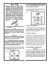
3-5 LOADER MOUNTED CONTROL
VALVE EQUIPPED WITH SINGLE LEVER
CONTROL HANDLE OR TRACTOR
REMOTE VALVE EQUIPPED WITH SIN-
GLE LEVER CONTROL HANDLE
If your loader utilizes a loader control valve equipped
with single lever control handle or tractor remote
valve equipped with single lever control handle, it will
function as shown in Figure 3-1.
3-7 NEUTRAL POSITION
The loader external valve provided by Bush Hog has
a “neutral position” which prevents movement of the
loader or attachment. When the control handle is
manually released from the work position, the valve
spool will return to the neutral position.
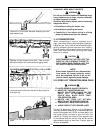
3-8 FLOAT POSITION
The loader external valve provided by Bush Hog has
a “float position” incorporated into the lift cylinder cir-
cuit which allows the loader to float. This float fea-
ture is important for satisfactory operation when
scraping, sweeping, leveling, or any job where it is
necessary to follow the contour of the surface. To
activate the float position, lower the bucket or attach-
ment and push the control handle all the way for-
ward into detent. The valve will stay in float detent
position until the operator manually pulls the control
handle out of detent position to deactivate float.
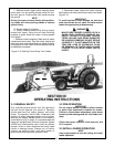
3-9 LOAD SENSE LOADER VALVE.
IMPORTANT
If your loader is equipped with a load sense type
control valve it may demonstrate the following
operation characteristic. Attempting to raise the
boom by finely feathering the control lever may
actually allow the boom to lower very slowly. To
prevent this from happening, move the control
lever far enough to ensure that the boom raises.
14
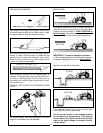
ESCAPING HYDRAULIC FLUID UNDER
PRESSURE CAN HAVE SUFFICIENT FORCE
TO PENETRATE SKIN, CAUSING SERIOUS
PERSONAL INJURY. BEFORE APPLYING
PRESSURE TO SYSTEM, BE SURE ALL
CONNECTIONS ARE TIGHT AND THAT
LINES, TUBES, AND HOSES ARE NOT DAM-
AGED. FLUID ESCAPING FROM A VERY
SMALL HOLE CAN BE ALMOST INVISIBLE.
USE A PIECE OF CARDBOARD OR WOOD,
RATHER THAN HANDS, TO SEARCH FOR
SUSPECTED LEAKS. IF INJURED BY
ESCAPING FLUID, SEE A DOCTOR AT
ONCE. SERIOUS INFECTION OR REACTION
CAN DEVELOP IF PROPER MEDICAL
TREATMENT IS NOT ADMINISTERED IMME-
DIATELY.
Figure 3-1
Figure 3-2
WARNING