


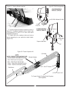
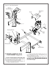
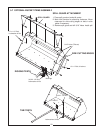


5-2 OPTIONAL HYDRAULIC VALVE
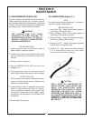
STAND ASSEMBLY (Figure 5-4)
A. Attach mounting plate to loader frame using
two 5/8 x 5-1/2” bolts, flatwashers, lockwashers and
nuts. Note that this plate may be rotated 180° to
allow three different mounting tube heights.
B. Attach mounting bracket to plate using two 1/2
x 1-1/2” bolts, lockwashers and nuts.
C. Attach mounting tube to bracket using 1/2 x 3”
bolts, lockwashers and nuts. The slotted hole also
requires a flatwasher, as shown.
D. Attach valve plate to tube using U-bolts, lock-
washers and nuts. Note: Mounting tube may be
too long for tractor being mounted and should be
cut to desired length.
Figure 5-4 Valve Stand Assembly
25
Shield
Operational
Decal
Valve
Plate
Tube
Mounting Plate
5/8 X 6-1/2”
Mounting Bracket
1/2 X 1-1/2”
1/2 X 3”
5/16 X 3”
5/16 X 1”
5/16 X 2-1/2”
(2)
Optional Brace
Optional
Mounting Bracket
3/8 x 1-1/4”
1/2 x 1-1/2”
5/8 x 6-1/2”
5/16 x 3”