


7
Charging/Recharging Using the 120 Volt AC Charger
and a Standard Household Extension Cord (not included)
1.Lift the AC Charger cover located on the back of the Electromate
®
and plug a standard North American 120 volt
AC extension cord into the 120 Volt AC Charger on the back of the unit. Plug the other end of the cord into a
standard 120 volt AC wall outlet.
2. Charge until one red, one yellow and one green LEDs light.
3. Once fully charged, disconnect the extension cord.
Note: The unit cannot be overcharged using the AC method.
12 Volt DC Charging
The DC recharging method will NOT recharge the unit as effectively as recharging from 120 volt AC. The 12 volt
DC recharging procedure is recommended only when it is necessary, since frequent use of the 12 volt DC
recharging procedure may shorten the battery system’s life.
1. Insert the gold-tipped DC/DC charging adapter plug into the vehicle’s 12 volt DC accessory outlet.
2. Insert the silver-tipped end plug into the 12 volt DC accessory outlet on the front panel of the unit.
3. To check the charge status of the battery during DC charging, disconnect the DC adapter from the accessory
outlet and push the Battery Charge Level pushbutton. Observe the battery charge indicator.
4. When charging is complete, remove the power cord.
CAUTION: TO REDUCE THE RISK OF PROPERTY DAMAGE: Do not recharge for more than 5 to 6 hours
maximum using the 12 volt DC method. Overcharging the battery using this method will shorten the battery life.
USING THE ELECTROMATE
®
AS A JUMP-STARTER
WARNING: Before using this system to jump-start any vehicle read and understand all instructions, safety tips,
warnings, cautions and first aid information provided in this manual and on the product labeling. Additional
important information may also be provided by the vehicle’s battery system manufacturer.
CAUTION: To avoid possible damage that may shorten the unit’s working life, protect this unit from direct
sunlight, direct heat and moisture. This system is to be used ONLY on vehicles, garden tractors and gasoline-
powered generators with 12 volt DC battery systems.
This system is NOT designed to be installed as a replacement for a vehicle battery.
• ONLY connect or disconnect battery leads when AC or DC charging supply cord is disconnected.
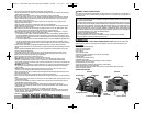
Jump-Starting Instructions
This jump-starter is equipped with a manual switch that only allows jump-start energy to flow when proper
connections are made to battery and frame.
Connect — Red clamp first, then black clamp. Disconnect — Black clamp first, then red clamp.
1. Turn OFF vehicle ignition and all accessories (radio, A/C, lights, cell phone, etc.). Place vehicle in “park” and
set the emergency brake.
2. Make sure jump-start system’s ON/OFF power switch is turned to OFF.
3. Connect jumper cables to unit.
4. To jump-start a NEGATIVE GROUNDED SYSTEM (NEGATIVE battery terminal is connected to the chassis —
the most common configuration), follow steps 4a and 4b, then proceed to step 6.
4a. Connect the positive (+) red clamp to vehicle battery’s positive ungrounded post.
4b. Connect the negative (–) black clamp to the vehicle chassis or engine block away from the battery. Do not
connect the clip to carburetor, fuel lines or sheet-metal body parts. Connect to a heavy gauge metal part of
the frame or engine block.
5. To jump-start a POSITIVE GROUNDED SYSTEM — In the rare event that the vehicle to be started has a
Positive Grounded System, positive battery terminal is connected to chassis, replace steps 4a and 4b above
with steps 5a and 5b, then proceed to step 6.
5a. Connect negative (–) black clamp to vehicle battery’s negative ungrounded post.
5b. Connect positive (+) red clamp to the vehicle chassis or engine block away from the battery. Do not
connect the clip to carburetor, fuel lines or sheet-metal body parts. Connect to a heavy gauge metal part of
the frame or engine block.
DO NOT TURN POWER SWITCH ON IF REVERSE POLARITY ALARM SOUNDS OR THE REVERSE POLARITY
INDICATOR LIGHTS. REVERSE THE CLAMP CONNECTIONS.
6. After making proper connections, turn power switch to ON.
7. Start vehicle (do not turn key for longer than 5-6 seconds).
8. After vehicle starts, turn the power switch to off, remove clamps (disconnect the frame or engine clamp first,
followed by the battery cable). Disconnect the cables from unit.
6
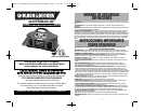
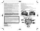
Front Panel
Air Inflator Nozzles
Protective Features
• Automatic Overload — Built-in protection against overload — in the event the AC outlet draws more than 400
watts, power to the unit’s outlet will automatically shut off.
• Ground Fault Circuit Interrupter (GFCI) — The GFCI protects the unit and the user by sensing imbalances in a
circuit caused by current leakage to the ground and shuts down the unit’s AC outlet to prevent electrical shock.
• Overheating — Unit automatically shuts down if it exceeds a safe temperature.
• Power Switch and Reverse Polarity Alarm — In event the cables/clamps are reversed during jump-starting, an
indicator lights and an alarm sounds BEFORE the Power Switch is turned ON.
• Low Battery — If the battery power level is too low, the AC Power Supply shuts down automatically.
AC AND DC CHARGING/RECHARGING
Use a common household AC extension cord for charging (cord not supplied).
For maximum battery life, we recommend the unit be kept fully charged at all times. If the battery is allowed to
remain in a discharged state, battery life will be shortened.
• MAKE SURE ALL SWITCHES ARE TURNED OFF DURING RECHARGING.
• Charge the unit for a full 48 hours using AC method before first use.
• Recharge the unit fully after each use.
• Recharge the unit every two months when it has not been used regularly.
The Electromate
®
also comes with a DC/DC charging adapter for recharging the unit from a 12 volt DC accessory
outlet in a vehicle.
If unit is fully discharged, it is recommended that the vehicle being used for recharging be left running while the
unit is charged via the 12 volt DC method.
IMPORTANT: If the unit’s AC Power Supply is switched ON during AC recharging, the unit will disable the
recharging process. To resume recharging, turn the AC Power Supply OFF.
Note: Recharging the battery after each use prolongs battery life; frequent discharges between recharges reduces
battery life.
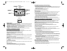
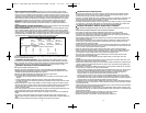
Viewing Battery Charge Status
Press the Battery Charge Level pushbutton to display battery status. The Battery Charge Level Indicator LEDS will
light.
LEDS (from right to left):
• Red LED indicates a low battery charge.
• One red and one yellow LED indicate a medium level or partially charged battery.
• One red, one yellow and one green LED indicates a full or high level battery charge.
JUMP-START SAFETY
ON/OFF SWITCH
REVERSE POLARITY
INDICATOR
BATTERY CHARGE
LEVEL INDICATORS
BATTERY CHARGE LEVEL
PUSHBUTTON
INFLATOR PRESSURE
GAUGE
ALTERNATOR CHECK
INDICATOR
AREA LIGHT ON/OFF SWITCH
INFLATOR ON/OFF
SWITCH
Front Panel
90556511 VEC026BD.qxp:VEC026BD ManualENSP 061808 12/11/09 2:02 PM Page 6