


Page 2
CHANNEL 3 OUTPUT: (Transmitter Only)
The Remote Transmitter of this system provides three radio frequency signals. The third signal of the transmitter may be used
to control an additional vehicle with a similar Audiovox PS-Series alarm or an optional Audiovox Remote Garage Door Opener
(AS-9154).
CHANNEL 3 OUTPUT (Transmitter Only) : Alternate Option
The transmitters included in this alarm incorporate an additional independent 3rd radio frequency channel. Although the alarm
module will only respond to 2 channels, the 3rd frequency can be programmed to an optional garage door interface (AS-9154).
The AS-9154 has its own on-board programmable receiver, and is designed to operate with most existing automatic garage door
openers.
In addition, the garage door interface receiver can be directly wired into the vehicle to offer a third remote control option. Since
this is a set of relay contacts, the receiver can be used to provide a selectable positive or negative pulse.
REMOTE ENTRY ILLUMINATION (Optional Relay Required) :
This system provides a ground output (300 mA maximum) to drive an external relay that can be used to illuminate the dome light
for 30 seconds whenever the system is disarmed.
This circuit will flash the interior dome light when the alarm is triggered. Since a relay is required (not included), this feature can
be used with both positive and negative switched dome light circuits.
DOOR LOCK / UNLOCK OUTPUTS:
This system provides both (+) & (-) pulsed door lock outputs, for direct connection to mostOEM factory installed door lock control
relays. These outputs have a maximum current capability of 300 mA, therefore, external relays must be used on switching circuits
requiring more than 300 mA or with 4 or 5 wire polarity reversal door lock control circuits.
The optional AS-9159, Door Lock Interface, is available to simplify the wiring of these circuits.
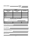
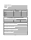
FUTURE REFERENCE CHART:
As an added convenience to the professional security installer, a chart has been printed in this guide for recording wire colors,
component mounting locations, and any other useful tips particular to the vehicle you are working on. Taking a few extra moments
on each installation to fill in the chart, can save you valuable time in the future.
TRANSMITTER PROGRAMMING:
The transmitters included in this kit have been programed at the factory for the Channel 1 (arm, disarm, and panic function) only.
Any additional programming, receiverChannel 2 or additional RF functions,must be programmed at the timeof installation. These
functions can be assigned to transmitter buttons #2 or #3.
Refer to the transmitter programming guide, included in this package, for more details regarding transmitter button assignments
and system functions.
SIREN:
Selecta mountinglocationin theenginecompartment thatis wellprotectedfrom accessbelowthe vehicle.Avoidareas nearhighheat
components or moving parts within the engine compartment. To prevent water retention, the flared end of the siren must be pointed
downward when mounted.
Mount the siren to the selected location using the screws and bracket provided.
CONTROL MODULE:
Select a mounting location inside the passenger compartment (up behind the dash), and secure using two screws provided.
The control module can also be secured in place using cable ties.
Donot mountthecontrolmodule intheengine compartment,asit isnotwaterproof. Youshouldalso avoidmountingtheunit directly
ontofactoryinstalledelectroniccomponents. ThesecomponentsmaycauseRFinterference,whichcanresultinpoortransmitterrange
or intermittent operation.
INSTALLATION OF MAJOR COMPONENTS: