


6
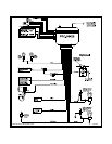
OPTIONAL SHOCK SENSOR
4-PIN White Plug w/4 Wires; Red, Black, Blue, and Green
The Red (+12 volt), Black (ground), Blue (pre-detect) and Green (full trigger when armed) wires loaded into the
white connector shell are the inputs/outputs of the shock sensor. Route the 4 wire harness from the shock sensor
location to the Control Module and plug the 4-PIN white connector into the mating 4-PIN connector.
VALET/PROGRAM/MANUAL OVERRIDE SWITCH
2-PIN Blue Plug w/2 Wires; Black and Gray
The Black and Gray wires in the 2-PIN blue connector are the ground supply and Valet/Program input of the unit.
When the Gray wire is grounded, under certain conditions, the unit will enter the valet mode. When the Gray wire is
sequentially grounded under other conditions, the unit will enter the various program modes. Route the Black and
Grey wires from the Valet/Program/Manual Override switch to the unit and plug the blue 2-PIN connector into the
mating blue connector shell of the control module. Do not force the connector, it will only plug in one way.
Note: Please refer to the section; "Programming System Features" shown later in this installation guide to learn
the operation of the valet/program/manual override switch.
POWER DOOR LOCK HARNESS
2-PIN White Plug w/2 Wires; Red & Green
The connection of the power door lock/unlock wires has already been explained. Route the Red and Green wires
to the unit and plug the white 2-PIN connector into the mating white two pin connector shell of the control module.
Do not force the connector, it will only plug in one way.
PROGRAMMING FEATURES:
There are five (5) Programmable Features on this system. Study the list below, keeping in mind the features and
their defaults, (how it comes programmed from the factory) and decide how best to program the unit for your
particular installation.
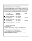
Programmable Features:
Features 1 Chirp 2 Chirp Default
First Passive Arming Active Arming Passive Arming
Second Ignition D/L ON Ignition D/L OFF Ignition D/L OFF
Third Ignition D/UL ON Ignition D/UL OFF Ignition D/UL OFF
Fourth Passive D/L Active D/L Active D/L
Fifth Chirps ON Chirps OFF Chirps ON
To Program These Features:
Entering the Programming Mode involves operating the Ignition Switch and the Valet/Program/Manual Override Switch
in a particular sequence. This sequence is very time dependent, in other words it must be performed
quickly in
order for you to enter the mode. This sequence is also only one step different from the Transmitter Programming
Mode, so make certain you perform the sequence properly.
Upon entering the Programming Mode, the system is immediately set to allow adjustment of the First Program-
mable Feature. That First feature, "Passive or Active Arming", can then be set ON or OFF by pressing button 1 of the
transmitter. The system confirms that it is set to adjust the First feature by repeatedly flashing the LED once, with
a pause in between each flash. The system will then report how the feature has been set by the number of chirps
heard after pressing the transmitter button. Toggling the Valet/Program/Manual Override Switch once again will
advance you to the Second Programmable Feature, confirmed by a repeating two LED flashes, with a pause in
between each flash, etc., etc.
It is important to note that when you first enter the Programming Mode, you are automatically positioned to adjust
the First Programmable Feature and that the Valet/Program/Manual Override Switch allows you to toggle from
there through each of the four more programmable features. However, it will not allow you to return to any feature