


5
5
+12VDC source. Connect the common, normally open, and normally closed contacts of the relay to perform the
selected function of Channel 3.
DOOR LOCK/UNLOCK CONTROL HARNESS (+) and (-)
2-PIN White Plug w/2 Wires; RED & GREEN
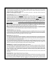
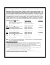
The Red and Green Door Lock/Unlock output wires provide either a momentary pulsed ground (-) or a momentary
pulsed 12VDC (+) output for controlling a vehicle's power door lock/unlock circuit. In order to accomplish this "dual
polarity" output scheme these two wires produce the opposite polarity at the opposite time. To better understand
this, refer to the table below:
The output of these wires has a maximum switching capability of 300mA. Many vehicles today have factory door
lock relays which can be connected directly to these outputs, however always confirm that the factory relays in your
particular vehicle do not exceed the rated 300mA output of the units door lock/unlock circuit. Plug the two pin
connector of the door lock/unlock harness into the mating connector shell of the control module. Determine the
door lock circuit of the vehicle you are working on and wire according to the diagrams shown.
WIRING FOR "GROUND PULSE" DOOR LOCK CIRCUITS:
This is a system commonly used on most import vehicle's factory door lock/unlock systems and with a few
domestic vehicles which employ factory "keyless entry" systems. In this application, the Red wire serves as the
"Lock" output, providing a ground pulse during the arming sequence and the Green wire serves as the "Unlock"
output, providing a ground pulse during the disarming sequence.
Connect the Red wire to the low current ground factory door "Lock" signal wire leading from the factory switch to the
factory door lock relay. Connect the Green wire to the low current ground factory door "Unlock" signal wire leading
from the factory switch to the factory door unlock relay.
WIRING FOR "POSITIVE PULSE" DOOR LOCK CIRCUITS:
This is a system commonly used on many domestic vehicle's factory door lock/unlock systems, particularly
General Motors and Chrysler, although not on all models. (Please see the note regarding "5-Wire Reverse Polarity
Door Lock Systems"). In this application, the Green wire serves as the "Lock" output, providing a positive pulse
during the arming sequence and the Red wire serves as the "Unlock" output, providing a positive pulse during the
disarming sequence.
Connect the Green wire to the low current positive (+12VDC) factory door "Lock" signal wire leading from the factory
switch to the factory door lock relay. Connect the Red wire to the low current positive (+12VDC) factory door "Unlock"
signal wire leading from the factory switch to the factory door unlock relay.
4 WIRE POLARITY REVERSAL and 5 WIRE ALTERNATING DOOR LOCK CONTROL CIRCUITS:
In these applications, the AS-9159 Door Lock Interface (or equivalent 30 Amp. automotive type relays) must be used.
Refer to the Audiovox Door Lock Wiring Supplement for proper connection to these types of circuits.
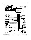
PLUG-IN CONNECTIONS AND COMPLETING THE INSTALLATION:
Now that all the other components have been installed and most of the main connections completed, it is time to
finish connecting the remaining plug-in components and completing the installation. Even though these are plug-
in connections and the plugs have been shaped such that they cannot be plugged in wrong, please read and
follow the instructions below for each connection to make certain each component is properly installed.
DASH MOUNTED LED
2-PIN White Plug w/2 Wires; Red and Blue
The Red and Blue wires in the 2-PIN mini white connector control the anode and cathode of the dash mounted
LED. Route the twin lead Red and Blue wires from the LED to the control unit and plug the two pin connector into
the mating white mini connector shell of the control module. Do not force the connector, it will only plug in one way.
Wire Color Function Polarity
Red Lock Ground (-)
Red Unlock Positive (+)
Green Lock Positive (+)
Green Unlock Ground (-)