


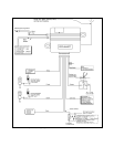

DARKBLUE WIRE:CHANNEL 2OUTPUT
The dark blue wire pulses to ground via an independent RF channel from the keychain transmitter. This is a
transistorized, low current (300 mA) output, and should only be used to drive an external relay coil or trigger inputs for
optional devices.
WARNING:Connectingthe darkbluewiretothehighcurrent switchedoutputoftrunkreleasecircuits willdamage
the control module.
Connect the dark blue wire to terminal 86 of the AS-9256 relay (or an equivalent 30 Amp. automotive relay), connect
terminal 85 of the relay to a fused +12 VDC battery source,and wire the remaining relay contacts to perform the selected
function of channel 2.
GREY&BLACK2PIN(blue)CONNECTOR:VALETSWITCH
Route the two conductor, blue connector from the valet switch to the control module, and plug it into the mating blue
connector on the end of the module.
RED&GREEN2PIN (white)CONNECTOR:DOORLOCKOUTPUTS
These wires will provide either a pulsed ground output to the factory door lock control relay, or a pulsed +12 VDC output
to the factory door lock control relay. In either case, the maximum current draw through these outputs must not exceed
300 mA.
3WIREGROUNDSWITCHEDDOORLOCKS
TheRedwireprovidesa groundpulseduringlocking. Connectthe Redwiretothewirethatprovidesalowcurrentground
signal from the factory door lock switch to the door lock control relay.
TheGreenwireprovidesa groundpulseduringunlocking. Connectthe Greenwiretothewirethatprovidesalowcurrent
ground signal from the factory unlock switch to the door unlock control relay.
3WIREPOSITIVESWITCHEDDOORLOCKS
The Red wire provides a positive +12 VDC pulse during unlocking. Connect the Red wire to the wire that provides a
low current positive signal from the factory door unlock switch to the door unlock control relay.
The Green wire provides a positive +12 VDC pulse during locking. Connect the Green wire to the wire that provides
a low current positive signal from the factory door lock switch to the door lock control relay.
4WIREPOLARITYREVERSALand5WIREALTERNATINGDOORLOCKCONTROLCIRCUITS
In these applications, the AS-9159 Door Lock Interface (or equivalent 30 Amp. automotive type relays) must be used.
Refer to the Audiovox Door Lock Wiring Supplement for proper connection to these types of door lock circuits.
COMPLETING THE INSTALLATION:
ANTENNA WIRE : Be sure to extend the thin Black antenna wire to it's full length, and cable tie in place where it cannot
be damaged. Avoid wrapping this wire around major high current wiring looms.
WIRE DRESSING : Always wrap the system's wires in convoluted tubing, or with a spiral wrap of electrical tape, and
secure these looms along the routing using cable ties.
OPERATION : Take a few moments to check off the appropriate option boxes in the owner's manual, and to fully explain
the operation of the system to your customer.
3