


VALETSWITCH:
Select a mounting location for the switch that is easily accessible to the driver of the vehicle.
The switch does not have to be concealed, however concealing the switch is always recommended, as this provides
an even higher level of security to the vehicle.
The switch is mounted by drilling a 1/4" diameter hole in the selected location. Be sure to check behind the dash for
adequate clearance for the body of the switch, and to confirm the drill will not damage any existing components as it
passes through the dash.
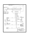
WIRING THE SYSTEM:
REDw/WHITE TRACEFUSED WIRE:+12 VDCCONSTANTBATTERY SOURCE
Connect the Red w/White tracer wire to a +12 VDC battery source.
YELLOW WIRE : +12 VDC IGNITION SOURCE
Connect this wire to a source that has + 12 volts when the key is turned to the start and run positions, and has 0 volts
when the key is in the off position.
BLACKWIRE:CHASSISGROUND
Connect this wire to a solid, unpainted, metal part of the vehicle's chassis.
Do not confuse this wire with the thin black antenna wire that exits the control module independently.
PURPLEWIRE :+DOOR TRIGGER
If the vehicle's door courtesy light switches +12 volt to the interior light circuit when a door is opened, connect the Purple
wire to the positive switched wire from the driver's door pin switch.
WARNING: Do not use the purple wire if the vehicle has ground output type door switches. (see BROWN WIRE)
BROWN WIRE: -DOOR TRIGGER
If the vehicle's door courtesy light switches ground to the interior light circuit when a door is opened, connect the Brown
wire to the ground switched wire from the driver's door pin switch.
WARNING: Do not use thebrown wire if the vehicle has +12 voltoutput type door switches. (see PURPLE WIRE)
NOTE: In all installations, either the Purple or Brown door pin switch wires must be used. This wire prevents
automatic locking of the doors if the ignition is turned on while the door is open or ajar.
ORANGE WIRE : 300 mA GROUND OUTPUT WHEN LOCKED
This is the output control for the starter cut relay. Connect the Orange wire to terminal 86 of the AS-9256 relay (or an
equivalent 30 Amp. automotive relay). Wire the remaining relay contacts as shown in the wiring diagram.
DARKGREENw/WHITETRACEWIRE:ENTRYILLUMINATION
This wire provides a 30 second ground signal whenever the doors are unlocked using the remote transmitter, and is
used to control the optional entry illumination feature. This output is also used to provide feedback information when
programming the transmitters.
This is a low current (300 mA) transistorized output, and should only be used to drive an external relay coil. Connect
the Dark Green w/White trace wire to terminal 86 of the AS-9256 relay (or an equivalent 30 Amp. automotive relay),
connect terminal 85 of the relay to a fused +12 VDC battery source, and wire the normally open and common (87 & 30)
relay contacts according to the polarity of the vehicle's courtesy light circuit.
2