


LIGHT GREEN Wire : Ignition 2 Output
Connect this wire to the ignition 2 wire from the ignition switch. This wire will show +12 Volts when the ignition
key is turned to the “ RUN or ON “ position, and in some cases, the “ START or CRANK “ position. This wire
will show 0 Volts when the key is turned to the “ OFF “ and “ ACCESSORY “ positions.
NOTE: The PRO-9171FT ignition 2 output can be programmed to remain ON while the starter is cranking. The
factory default setting for ignition 2 is to show 0 volts while the starter is cranking.
This output should be programmed at time of installation and should simulate the ignition 2 source in the vehicle
when the ignition key is used to start.
VIOLET Wire : Accessory Output
Connect this wire to the accessory wire from the ignition switch. This wire will show +12 Volts when the ignition
key is turned to the “ ACCESSORY “ and “ RUN or ON “ positions, and 0 Volts when the key is turned to the
“ OFF “ and “ START or CRANK “ positions.
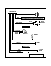
WIRING CONNECTIONS: 12 Pin Input / Output Harness
BLACK Wire: Chassis Ground Source
Connect this wire to a solid, clean chassis ground source.
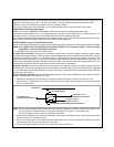
BLACK w/WHITE Tracer Wire: Control Switch
The Black w/ White tracer wire provides ON-OFF control of the Remote Starter.
When the Black w/ White wire is switched to a full time ground, the PRO-9171FT Remote Start Module is
operative. When the Black w/ White wire is at open circuit through the control switch, the remote starter is
disabled.
Connect the Black w/ White tracer wire to one of the terminals from the back of the control switch. Connect the
remaining terminal on the control switch to chassis ground. Always try to mount the switch so that the ON
position is in an upward direction.
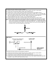
GREY Wire: Negative Inhibit Input 1
Connect the GREY wire to the hood pin switch provided . This wire will be routed through the fire wall into the
engine compartment. It is necessary to use an existing grommet when passing wires through the fire wall to
prevent short circuiting. This is an important safety feature of PRO- 9171FT, and failure to use this feature can
result in serious injury. In some cases, the bracket provided may be required to facilitate mounting of the hood
pin switch.
GREY w/BLACK TracerWire: Negative InhibitInput 2
Any time the grey w/ black tracer wire is grounded, the Remote Starter will stop operating, even if the signal is
received from the transmitter.
If the brake light switch in the vehicle switches ground to the brake light circuit, connect the Grey w/ Black trace
wire to the output of the brake light switch. If the brake light switch in the vehicle switches +12 Volts, do not use
the Grey w/ Black wire; see Brown w/ Black tracer wire.
BROWN Wire:Positive Inhibit Input 1
Any time + 12 Volts is applied to the Brown wire, the Remote Starter will stop operating, even if the signal is
received from the transmitter.
If the vehicle has a factory installed hood pin switch, and that switch provides + 12 Volts to an under hood light,
the Brown wire can be connected to the existing pin switch.
BROWN w/ BLACK Tracer Wire: Positive Inhibit Input 2
Any time + 12 Volts is applied to the Brown w/ Black tracer wire, the Remote Starter will stop operating, even
if the signal is received from the transmitter. If the brake light switch in the vehicle switches + 12 Volts to the brake
light circuit, connect the Brown w/ Black trace wire to the output of the brake light switch. If the brake light switch
in the vehicle switches ground, do not use the Brown w/ Black wire; see Grey w/ Black tracer wire.
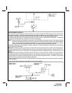
YELLOW w/ BLACK Tracer Wire: + 12 Volt Alarm By - Pass Output
NOTE: YOU MUST DISCONNECT THE IGNITION INPUT OF THE ALARM FROM ANY OTHER WIRE THAT
IT IS PRESENTLY CONNECTED TO IN THE VEHICLE.
3