


5
wire that provides a low current positive signal from the factory door lock switch to the factory door lock control relay.
3 Wire Positive Switched 2 Step Door Locks
The green wire provides a positive pulse during locking, or the pulsed + 12 volt lock output. Connect the green wire to the
wire that provides a low current positive signal from the factory door lock switch to the factory door lock control relay.
The red wire provides a positive pulse during unlocking, or the drivers door pulsed positive unlock output. Connect this
wire to the drivers door unlock relay that requires a low current positive signal to unlock only the drivers door. If the vehicle
does not have a separate drivers door relay, one will have to be added. Locate the drivers door unlock motor wire and cut
it at a convenient location to allow wiring of an optional relay. Connect the door side of the cut wire to terminal 30 of the
optional relay added. Connect the vehicle side of the cut wire to terminal 87a of the optional relay added. Connect the red
wire of the 3 pin harness to terminal 86 of the optional relay added. Connect terminal 85 of the optional relay added to
chassis ground. Most vehicles door lock/unlock motor legs rest at ground, and switch +12 volts to the door lock/unlock
motor legs for operation, if this is the case in the vehicle you are working on, connect the remaining terminal 87, to a fused
+ 12 volt source. In the rare instance that the vehicle door lock/unlock motor legs rest at + 12 volts and switches ground to
the door lock/unlock motors, connect he remaining terminal 87, to chassis ground.
The Green/Black wire provides a pulse ground output when the locking/unlock button of the transmitter is pressed a second
time after unlocking the driver's door. Because the vehicle you are working on requires a positive pulse from the factory
door lock switch to the factory door lock control relay, you will have to add a relay to invert the output polarity of this wire.
Connect the Green/Black wire to terminal 86 of the optional added relay. Connect terminal 85 & 87 to a fuse + 12 volt
source. Connect terminal 30 to the low current door unlock wire from the factory door switch to the door unlock control relay.
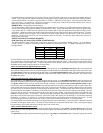
Resistive Circuits, As Well As 4 Wire Polarity Reversal and 5 Wire Alternating 12 Volt Door Lock Control Circuits
These applications require the use of additional components which may include relays or fixed resistors.
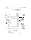
PLUG-IN CONNECTIONS AND COMPLETING THE INSTALLATION:
Now that all the other components have been installed, and most of the main connections completed, it is time to finish
connecting the remaining plug-in components and completing the installation. Even though these are plug-in connections, and
the plugs have been shaped such that they cannot be plugged in wrong, please read and follow the instructions for each
connection to make certain each component is properly installed.
DASH MOUNTED LED
2PIN White Plug w/2 Wires; Red & Blue
The Red & Blue wires in the 2PIN mini white connector control the anode and cathode of the dash mounted LED. Route the
twin lead Red and Blue wires from the LED to the control unit and plug the two pin connector into the mating white mini
connector shell of the control module. Do not force the connector, it will only plug in one way.
VALET/PROGRAM/MANUAL OVERRIDE SWITCH
2PIN Blue Plug w/2 Wires; Black & Gray
The Black & Gray wires in the 2PIN blue connector are the ground supply and Valet/Program input of the APS-45 unit.
When the Gray wire is grounded, under certain conditions, the unit will enter the valet mode. When the Gray wire is
sequentially grounded under other conditions, the unit will enter the various program modes. Route the Black and Grey
wires from the Valet/Program/Manual Override switch to the APS-45 unit and plug the blue 2PIN connector into the mating
blue connector shell of the APS-45 control module. Do not force the connector, it will only plug in one way. Note: Please
refer to the section; "Programming System Features" shown later in this installation guide to learn the operation of the valet/
program/manual override switch.
POWER DOOR LOCK HARNESS
3PIN White Plug w/3 Wires; Red, Green, and Green/Black
The connection of the power door lock/unlock wires has already been explained. Route the Red, Green, and Green/Black
wires to the APS-45 unit and plug the white 3PIN connector into the mating white three pin connector shell of the APS-45
control module. Do not force the connector, it will only plug in one way.
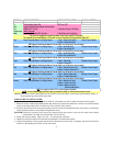
TRANSMITTER PROGRAMMING:
The transmitters supplied with the APS-45 are pre-programmed at the factory to provide the following function:
Button 1, pressed and released quickly = Lock & Unlock w/Siren or Horn Chirps
Button 1, pressed for ~ 2 second = Lock & Unlock w/o Siren or Horn Chirps
Button 1, pressed for ~ 3 seconds = Engage/Disengage Panic Mode
Button 2, pressed for ~ 3 seconds = Channel 2 Output
Buttons 1 & 2, pressed and HELD = Channel 3 Output