


The APS-45 Keyless Entry System is designed to provide a convenient electronic means to gain access to the vehicle by
providing RF remote control over the vehicle's power door lock system. The unit also includes outputs to control the
vehicle's dome lights, as well as exterior parking lights. Although not an alarm system, the APS-45 also incudes a starter
interrupt circuit output. It also includes two additional auxiliary outputs designed to allow for control over optional devices
such as a power trunk release or engine starting device.
BEFORE BEGINNING THE INSTALLATION:
1. Control Module
Dash Mounted L.E.D.
Valet / Manual Override Switch
2. Determine the type of factory power door lock system in use. Knowing the type of system up front before
beginning the installation can make the installation easier and faster since you can build whatever interface
(if needed) beforehand.
3. Determine whether the vehicle includes a power trunk release system, and if so what type it is.
INSTALLATION OF COMPONENTS:
CONTROL MODULE:
The Control Module is NOT waterproof, DO NOT mount it in the Engine Compartment. Select a mounting location under
the dashboard. Choose a mounting location that will not interfere with proper operation of the vehicle's steering column
mechanism, and brake and gas pedals. Secure the Control Module in the chosen location. Wait until all components have
been installed and all connections made before plugging in the main connectors.
DASH MOUNTED L.E.D.:
The small Red LED included in the kit serves as a visual indicator of the system's status and provides a visual deterrent to
a potential thief. The LED also provides important feed back information during the transmitter and feature program
modes. The LED should be installed in the dashboard in a highly visible area that may be seen from the driver’s seat as
well as from outside the vehicle. Try to choose a location close enough to the Control Module so that the LED's wires will
reach. Carefully inspect the area behind your chosen location to insure that the drill will not penetrate any existing factory
wiring or fluid lines. Drill a 1/4" hole and pass the connector end of the LED through the hole, and route the wires toward
the location of the Control Module. Press the LED firmly into place until it is fully seated.
VALET / MANUAL OVERRIDE SWITCH :
Since much of the use of this switch by the vehicle operator requires concurrent operation of the ignition key switch, it is
recommended that the Valet / Manual Override Switch be placed such that it can be reached by the driver's left hand, while
they operate the ignition key switch with their right hand. The switch can be mounted to the lower dash panel in the drivers
area. Inspect behind the chosen location to insure that adequate clearance is allowed for the body of the switch, and also
that the drill will not penetrate any existing factory wiring or fluid lines. Drill a 1/4" hole in the desired location and mount the
switch by passing it through the panel from the opposite side. Secure the switch using the nut, star washer, and on/off
face plate. It is suggested that the switch be oriented to allow the on position to be up toward the driver and the off position
to be down or away from the driver. Route the switch’s wires and connector toward the location of the Control Module.
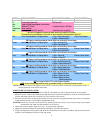
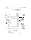
RED Wire (Connects to RED/WHITE wire at harness plug): Main 12 Volt Input Wire
These are the main power input wires for the APS-45 system. Both wires connect to a separate fuse holder contained in
the harness. These fuse holders each hold a separate ATC fuse, one 5AMP and one 10AMP. This RED wire must be
connected to a constant power wire at the vehicle's ignition switch harness or fusebox.
Locate a constant power wire at the vehicle's ignition switch harness. This wire will read +12VDC at all times, regardless
of the position of the ignition key switch. Attach the RED wire of the harness to this point by splicing and taping the
connection.
YELLOW Wire: Ignition Input Wire
This wire provides the APS-45 system with an ignition power input from the vehicle. Connect this wire to the Ignition wire
(primary ignition wire) from the ignition switch. This vehicle wire will show +12VDC when the ignition key is turned to the
"ON" or "RUN" position
and
when turned to the "START" or CRANK" positions, and will have 0VDC when the key is turned
to the "OFF" and "ACCESSORY" positions.
Locate an ignition power wire at the vehicle's ignition switch harness. By splicing and taping the connection, attach the
YELLOW wire of the system to this point.
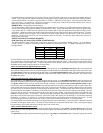
WHITE Wire: Positive Parking Light Flash Wire
This wire is designed to output a +12VDC positive light flash output, driven by the APS-45's internal relay, to be connected
directly to the vehicle's positive parking light circuit. Once the wire is located, confirm that all the vehicle's parking lights will
illuminate when +12VDC is connected to it.
NOTE: Some vehicles, (mostly European) have isolated "left" and "right" side parking lights. To connect to the parking
2