


128-6453
3 of 8
Page 3
VALET SWITCH:
Select a desired mounting location for the switch, that is easily accessible to the driver of the vehicle.
The switch does not have to be concealed, however, concealing the switch is always recommended, as this
provides an even higher level of security to the vehicle. The switch may be mounted in or below the dash by drilling
a 1/4" diameter hole in the location. Be sure to check behind the dash for adequate clearance for the body of
the switch, and to confirm that the drill will not damage any existing components as it passes through the dash.
Route the connector and wires toward the module and plug the connector into the appropriate connector on the
module.
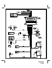
WIRING THE SYSTEM:
WHITE WIRE: + 12 VDC PULSED PARKING LIGHT OUTPUT ( 15 A MAX )
This wire is provided to flash the vehicle’s parking lights. Connect the white wire to the positive side of one of
the vehicle’s parking lights.
RED FUSED WIRE - (VOLTAGE SENSING): + 12 VDC CONSTANT BATTERY SOURCE
This wire controls the sensitivity of the voltage sensing circuit, which detects the turning on of an interior light
when a door is opened. It will also detect the switching on of parking or headlamps, and in many cases will trigger
the alarm when a thermostatically controlled electronic radiator cooling fan switches on. It is recommended that
when installing this system into vehicles with electronic “after fans”, the procedure for RED FUSED WIRE -
(HARDWIRE) should be followed.
In voltage sensing applications, the closer to the battery that the red wire is connected, the less sensitive the
voltage sense circuitry will be. Moving this connection point to the fuse panel will increase the sensitivity and
connecting to the courtesy lamp fuse in the vehicle will provide maximum sensitivity of the voltage sense circuit.
RED FUSED WIRE - (HARDWIRE): + 12 VDC CONSTANT BATTERY SOURCE
When hardwiring the control module to pin switches at all entry points, the voltage sense circuit must be disabled.
Set programming feature # 6 to the "OFF" position. Connect the red wire to a + 12 VDC constant battery source.
DARK BLUE WIRE: 300 mA PULSED OUTPUT/CHANNEL 2
The dark blue wire pulses to ground via an independent RF channel from the keychain transmitter. This is a
transistorized, low current output, and should only be used to drive an external relay coil.
WARNING: Connecting the dark blue wire to the high current switched output of trunk release circuits
or some remote starter trigger inputs, will damage the control module.
Connect the dark blue wire to terminal 86 of the AS-9256 relay (or equivalent 30 A automotive relay) and wire
the remaining relay contacts to perform the selected function of channel 2.
WHITE w/ BLACK TRACE WIRE: POSITIVE OUTPUT TO SIREN
Route this wire through a rubber grommet in the firewall to the siren location. Connect the white/black wire to
the positive wire of the siren. Secure the black ground wire of the siren to chassis ground.
BLACK WIRE: CHASSIS GROUND
Connect this wire to a solid, metal part of the vehicle’s chassis. Do not confuse this wire with the thin black
antenna wire that exits the control module independently.
YELLOW WIRE: + 12 VDC IGNITION SOURCE
Connect this wire to a source that supplies 12 VDC when the ignition key is in the ON and CRANK positions
and off when the key is in the OFF position.