


128-6453
2 of 8
Page 2
CHANNEL 2 OUTPUT:
This system provides an additional hardwire remote output to control an assortment of optional upgrades.
This output is an independent channel from the transmitter and is controlled by button #2 or the combination
of button 1 & 2 dependent on the programming of the transmitter as set up by your installation center. It is a
delayed ground pulse (300 mA maximum) and can be used to control:
• Optional trunk release relay AS-9256
• Optional remote starter AS-9075
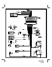
INSTALLATION OF MAJOR COMPONENTS:
CONTROL MODULE:
Select a mounting location inside the passenger compartment (up behind the dash) and secure using two
screws provided.
The control module can also be secured in place using cable ties.
Do not mount the control module in the engine compartment, as it is not waterproof. You should also avoid
mounting the unit directly onto factory installed electronic components. These components may cause RF
interference, which can result in poor transmitter range or intermittent operation.
SIREN:
Select a mounting location in the engine compartment that is well protected from access below the vehicle. Avoid
areas near high heat components or moving parts within the engine compartment. To prevent water retention,
the flared, or opened end, of the siren must be pointed downward when mounted. Mount the siren to the selected
location using the screws and bracket provided.
HOOD OR TRUNK PIN SWITCH:
A pin switch is included for use in protecting the hood or trunk (or hatchback) of the vehicle.
The switch must always be mounted to a grounded, metal surface of the vehicle. It is important to select a location
where water cannot flow or collect and to avoid all drip “gutters” on hood and trunk fender walls. Choose locations
that are protected by rubber gaskets when the hood or trunk lid is closed.
The pin switch can be mounted using the bracket provided or direct mounted by drilling a 9/32" diameter
mounting hole.
Keep in mind that when properly mounted, the plunger of the pin switch should depress at least 1/4" when the
hood or trunk lid is closed.
DASH MOUNTED LED:
A small red LED is included that will serve as a visual indicator of the alarm status. It should be installed in the
dash, located where it can be easily seen from outside the vehicle, yet not be distracting to the driver.
Once a location has been selected, check behind the panel for wire routing access and to confirm the drill will
not damage any existing components as it passes through the panel.
Drill a 1/4" diameter hole and pass the red and blue wires from the LED through the hole, from the front of the
panel. Firmly press the body of the LED into the hole until fully seated.
SHOCK SENSOR:
Select a solid mounting surface for the shock sensor on the firewall inside the passenger compartment and
mount the sensor using the two screws provided. The shock sensor can also be secured to any fixed brace
behind the dash using tie straps.
Whichever mounting method is selected, make certain that the sensitivity adjustment is accessible for use
later in the installation.