


CHANNEL 2 OUTPUT:
This system provides an additional hardwire remote output to control an assortment of optional upgrades.
Thisoutputis anindependentchannelfromthe transmitter,andiscontrolledbybutton #2onthetransmitter. It isadelayed
ground pulse (300 mA maximum), and can be used to control:
Optional trunk release relay AS-9256
Optional remote starter AS-9151
Optional window roll up AS-9153
Page 2
DASH MOUNTED L.E.D.:
A small red L.E.D. is included that will serve as a visual indicator of the alarm status. It should be installed in the dash,
located where it can be easily seen from outside the vehicle, yet not be distracting to the driver.
Once alocationhas beenselected,check behindthe panelforwire routingaccess,and toconfirm thedrillwill notdamage
any existing components as it passes through the panel.
Drill a 15/64" diameterhole, and pass the redand blue wires from theL.E.D. through the hole, from thefront of the panel.
Firmly press the body of the L.E.D. into the hole until fully seated.
SIREN:
Select a mounting location in the engine compartment that is well protected from access below the vehicle. Avoid areas
near high heat components or moving parts within the engine compartment. To prevent water retention, the flared end
of the siren must be pointed downward when mounted.
Mount the siren to the selected location using the screws and bracket provided.
CONTROL MODULE:
Select a mounting location inside the passenger compartment (up behind the dash), and secure using two screws
provided.
The control module can also be secured in place using cable ties.
Do not mount the controlmodule in the engine compartment, asit is not waterproof. You shouldalso avoid mounting the
unit directly onto factory installed electronic components. These components may cause RF interference, which can
result in poor transmitter range or intermittent operation.
INSTALLATION OF MAJOR COMPONENTS:
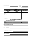
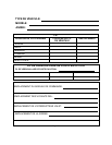
FUTURE REFERENCE CHART:
As an added convenience to the professional security installer, a chart has been printed in this guide for recording wire
colors, component mounting locations, and any other useful tips particular to the vehicle you are working on. Taking a
few extra moments on each installation to fill in the chart, can save you valuable time in the future.
HOOD OR TRUNK PIN SWITCH:
A pin switch is included for use in protecting the hood or trunk (or hatchback) of the vehicle.
The switch mustalways be mounted to agrounded, metal surface ofthe vehicle. It isimportant to select a locationwhere
water cannot flow or collect, and to avoid all drip “gutters” on hood and trunk fender walls. Choose locations that are
protected by rubber gaskets when the hood or trunk lid is closed.
The pin switch can be mountedusing the bracket provided, or direct mounted by drillinga 9/32" diameter mounting hole.
Keep in mind that when properly mounted, the plunger of the pin switch should depress at least 1/4" when the hood or
trunk lid is closed.
VALET SWITCH:
Select a desired mounting location for the switch, that is easily accessible to the driver of the vehicle.
The switch does not have to be concealed, however, concealing the switch is always recommended, as this provides
an even higher level of security to the vehicle. The switch may be mounted below the dash using one of the brackets
provided, or mounted in the dash by drilling a 1/4" diameter hole in the location. Be sure to check behind the dash for
adequate clearance for the body of the switch, and to confirm that the drill will not damage any existing components as
it passes through the dash.
Whichever mounting method is used, make certain the back of the switchis accessible for wiring later in the installation.