


8
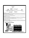
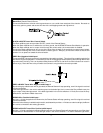
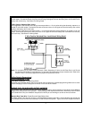
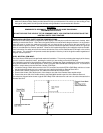
DARK GREEN/ORANGE Wire: Tach Sensor Input
This wire will continually monitor the engine tach rate while the unit is under power of the Remote Start module. This
wire will be routed to the vehicle ECM tach input or through the firewall into the engine compartment and connect to
the negative side of the ignition coil. This Remote Start unit learns the tach rate of the vehicle and in most cases will
operate properly from a single coil, single injector, or one multi coil pack regardless of the number of cylinders. In
certain vehicle with a single coil for each cylinder, it may be necessary to connect this wire to more than one cylinder
for proper tach reference. See multi coil wiring detail shown later in this manual for additional information. (See
feature # 10 for OVERCRANK information)
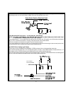
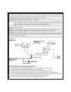
2 Pin Door Lock/Unlock Harness: (White Connector)
The Red & Green Door Lock/Unlock output wires provide either a pulsed ground or pulsed + 12 volts to control the
vehicle door lock / unlock circuits. The output of these wires has a maximum switching capability of 300mA. Many
vehicles today have factory door lock relays which can be connected directly to these outputs, however always
confirm that the factory relays in your particular vehicle do not exceed the rated 300mA output of the units door lock/
unlock circuit. Plug the two pin connector of the door lock/unlock harness into the mating connector shell of the control
module. Determine the door lock circuit of the vehicle you are working on and wire according to the diagrams shown.
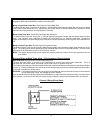
3 Wire Ground Switched Door Lock Circuits:
In this application, the Red wire of the two pin harness provides a ground pulse during the arming sequence, or pulsed
ground lock output. Connect the Red wire to the low current ground signal wire from the factory door lock switch to the
factory door lock relay.
Tachometer Input Wiring Detail
3 Wire Ground Switched Door Lock/Unlock Wiring Detail